I really just want to play with the fundamental components inside an amplifier.
What kind of power supply has a good negative rail?
What I would recommend is you make a small single rail power supply using a small transformer and bridge rectifier. There are only three components, the tranny, the bridge and a reservoir cap. A small tranny gives inherent "short circuit protection" for many seconds... and believe me, you will short things out and have transistors fail short. You don't want some fancy switching or computer PSU that can supply oodles of current and then explode in a graveyard of burnt silicon.
Single rail amps are easier to get to grips with, infinitely safer for your speakers and will teach you much of the basics.
Using an ATX supply to "play" is just fine since they usually have short circuit protection and good regulation. There's no need to make anything more complicated than needed to do a little hands on learning.
Hadn't seen your post
")
Yes, that's exactly the simple kind of amp to build.
Using an ATX supply to "play" is just fine since they usually have short circuit protection and good regulation. There's no need to make anything more complicated than needed to do a little hands on learning.
Hi, if I breadboard this out, could I just used an mp3 player? Or would I need a preamp? (I'm guessing the first transistors boost the second set)
You only need a preamp if you are using a magnetic phonograph cartridge or a dynamic microphone. Computer output, , AM/FM radio earphone jack, MP3 player earphone jack, the signal may ba a little high voltage for these inputs and need to be lowered with an input potentiometer between signal and ground. The wiper of the pot goes to the amp input jack. That is if you turn those three up too loud, which might be 6 VAC or something. CD player line out and preamp output, the signal is 1 to 2 VAC out, which is probably what these designs are expecting on the input.
I have found breadboard construction much too unreliable to fool with. You can buy vector board with holes for about $10, but I take plastic sheet and drill holes in it for this sort of thing. If you are not using DIP packages, which tend to short across the plastic between pins in polycarbonate (Lexan). For close DIP connections (like on op amps) I use 1/16" NEMA C laminate material from mcmaster.com. A little kynar or teflon solid core insulated wire is useful for connections between components where you need to jumper a wire, you can't just twist the leads together and solder. Old 28 ga wire wrap wire is nice for not burning when you hit it with the iron. Alpha teflon insulated 24 ga wire is about $.60 a foot, I have a roll of it but only two colors.
I like a Weller WP35 iron, and tin lead rosin core solder, not the ROHS compliant silver solder.
Have fun.
Last edited:
What do you mean by "the point at which it turns on"? What do you define as "on"? You're aware of the transistor equations, right?
You will often get an Vbe(on) or Vbe(sat) spec in datasheets, but that's relevant when using the transistor as a switch, not so much in linear operation. Depending on transistor size and Ic, Vbe tends to range in the 0.55-0.65 V vicinity when used in an amplifier.
Vce(sat) only indicates how far down the transistor can pull its emitter while conducting a given amount of current, which is important for power dissipation in switching applications.
Try and remember that transistors are "current driven". To turn on a transistor current has to flow in the base-emitter junction. A correspondingly larger current will then pass from collector to emitter. The base emitter voltage always bottoms out around 0.7 to 0.8 volts. You can't make the differential higher, all you can do is cause more current to flow.
There are three simple equations that can help
Ie = Ic + Ib
Ic = Ie - Ib
Ib = Ie - Ic
There are three simple equations that can help
Ie = Ic + Ib
Ic = Ie - Ib
Ib = Ie - Ic
I'm looking at data sheets.
Is the "Collector-Emitter Saturation Voltage:" the point at which it turns on??
If not, what is?
Do you have some parts already that you want to try and use and learn with, or are you looking for a complete design, and to try and build that ?
Im just randomly wondering around the internet trying to make sense of things.
Im a little over my head to be honest.
I was looking at this.
http://uk.mouser.com/ProductDetail/...ha2pyFadugQSyiJj/u6qxErnt3i6yi1R6785zV%2bWd0=
Collector-Emitter Saturation Voltage: 0.5 V
was wondering if that was what was needed to turn it on.
Im a little over my head to be honest.
I was looking at this.
http://uk.mouser.com/ProductDetail/...ha2pyFadugQSyiJj/u6qxErnt3i6yi1R6785zV%2bWd0=
Collector-Emitter Saturation Voltage: 0.5 V
was wondering if that was what was needed to turn it on.
Last edited:
No problem, anything your not sure over then just ask
The saturation voltage can be thought of like this...
Imagine a light switch that's turned on. Because its mechanical (two contacts that close) there is no voltage "lost" across the switch when its on. Its a perfect conductor. If that switch were a transistor, and we forced it to conduct as hard as we could, there would be a small voltage "lost" across it. That is the saturation voltage. Its small but in really high current applications significant because that voltage, and the current flowing through it, equals power lost which in turn equals heat generated and a loss of efficiency.
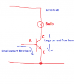
Here is an NPN transistor being used to turn a bulb on and off. By passing a small control current through the base-emitter path we cause a large current to flow in the collector-emitter.
Once we force the transistor fully on, if we measure the voltage across the collector and emitter we will measure the saturation voltage.
The voltage between base and emitter will never exceed around 0.7volts no matter how much current we try and force through.
If we reduce the current through the base emitter junction the transistor will only be partially on and the bulb will dim. The voltage "lost" is now over the collector and emitter. The base to emitter voltage will still be around 0.7 volts.
Attachments
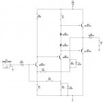
Okay, so this is a random class b amplifier....
These isnt much to it. And I understand that it wouldnt sound good.
But, if I wired this up with the right transistors, would it power a speaker / head phone?
An externally hosted image should be here but it was not working when we last tested it.
These isnt much to it. And I understand that it wouldnt sound good.
But, if I wired this up with the right transistors, would it power a speaker / head phone?
See it this way:I'm looking at data sheets.
Is the "Collector-Emitter Saturation Voltage:" the point at which it turns on??
If not, what is?
1) you have a transistor.
Emitter to ground, collector to a supply voltage, say +12V or whatever, but passing through a load, usually a resistor but in a power amp output it will be the speaker.
2) since no current is passing through the load, there is no voltage drop across it, so the collector receives the full +12V.
3) now you turn transistor ON, by applying some voltage to the base, or injecting some current into it (both things happen at the same time).
The transistor will now allow current to pass through it, so also into the load , which is in series with it.
The transistor is acting like a "faucet" , allowing that current to pass.
Voltage will appear across the load, so the transistor will get less than 12V.
In theory, when the transistor is heavily driven and it lets the load pass all the current it wants, the full 12V should drop across it and 0V across the transistor (from collector to emitter) .... but no, the transistor itself needs *some* voltage itself to pass that current, so even if you increase base current more and more, that voltage will not be any lower.
That is the saturation voltage.
And you can't just shrug and forget it, in large power transistors it can easily be 4 V , which must be substracted from the peak voltage available to your speaker.
So in a, say, +/-40V rails amp, you are losing 10% the peak voltage, 20% the available power, nothing to be despised.
It's not "just something the switching guys worry about" ... although of course they must be aware of it because it's one reason SMPS often are not as efficient as imagined.
Same goes to Class D amps, but really, it applies everywhere.
VERY important in low voltage (<13V) amps, such as car ones and all portables.
Imagine the trouble getting usable power in small radios powered by 2 AA batteries or cellphones powered by 3.6V Li Ion .
Last edited:

Using an ATX supply to "play" is just fine since they usually have short circuit protection and good regulation. There's no need to make anything more complicated than needed to do a little hands on learning.
thank you for posting the circuit jerluwoo!
could you explain what the R7/C1 network is for, and how to design such a network?
thank you very much!
- Status
- This old topic is closed. If you want to reopen this topic, contact a moderator using the "Report Post" button.
- Home
- Amplifiers
- Solid State
- super basic ab amplifier?