I don't have any data on that. I know that the results that I saw were not very impressive. My point here is simply not to assume that such and such a technology works because straight lines drawn on paper look so good. You have to provide decent measurements of the device or its just a guess how it will really work.
Basically the higher the frequency the more valid ray-tracing is, but also the more difficult it is to predict how the rays are emited from the source. So basically when the source and the device at a larger than a wavelength but not much larger than several wavelengths.
Basically the higher the frequency the more valid ray-tracing is, but also the more difficult it is to predict how the rays are emited from the source. So basically when the source and the device at a larger than a wavelength but not much larger than several wavelengths.
What are we to make, then, of Figure (2) and the surrounding discussion found on page 6 on the .pdf of this document?The world would be a much simpler place is we could do acoustics by simply drawing straight lines. Problem is that sound is waves not light rays and they don't work like light rays. They go arround corners and diffract at edges, all kinds of things that "rays" do not account for. So I simply discount any argument that uses "rays" to explain what happens. Like the "acoustic lens" thing that was shown earlier. Measurements of a real device show that it doesn't act much like it is supposed to except over a very narrow range of frequencies. But thats OK, it looks cool and marketing likes that - so it doesn't actually have to work. The real disappointing thing is that the techniques that actually do work aren't all that "cool" looking and tend to be much larger than we would like. So its just easier to do it wrong and looking good.
http://www.gedlee.com/downloads/Philosophy.pdf
Hi Art
The issue of hf absorption is a daunting one yet any improvement over what is available is appreciated. The only solution that seemed practical as a first shot was this one, a huge CD horn, a combination of a specific narrow pattern and lotsa driver horse power. I agree with a couple of your observations but can’t discuss them")
Hi Earl, all
What I was trying to explain earlier in this thread was that an acoustic reflector based system has the problem that the physical reflector is a fixed size while the frequency span means that the acoustic size is larger at higher frequencies and smaller at lower frequencies.
How large the reflector is acoustically governs how it reflects until it is very large where it acts more like a mirror (as in Earls Fig2) or it is very small like a small fraction of a wavelength where the pressure goes around the object.. The Paraline thing mentioned here uses path length only, no reflections and bends in the plane where the dimension is a fraction of a wavelength at 20Khz.
In the communications horn example earlier, the reflector is large enough compared to the wavelength to convert the expanding spherical wave into a plane wave beam with an off axis parabolic reflector.
The Zenith “circle of sound” speakers looked pretty cool back then anyway.
Heatmiser
I would agree with the link in general and would underscore the sound following the dotted lines are in stereo imaging terms “bad juju” but would add if you can position the far wall bounce to be behind you, that good too.
An equal loudness balloon would more clearly show why this kind of aiming works to maximize the width of the sweet spot (like if you have a couch) with any directional speaker and this works with narrower patterns as well..
Best
Tom Danley
The issue of hf absorption is a daunting one yet any improvement over what is available is appreciated. The only solution that seemed practical as a first shot was this one, a huge CD horn, a combination of a specific narrow pattern and lotsa driver horse power. I agree with a couple of your observations but can’t discuss them
Hi Earl, all
What I was trying to explain earlier in this thread was that an acoustic reflector based system has the problem that the physical reflector is a fixed size while the frequency span means that the acoustic size is larger at higher frequencies and smaller at lower frequencies.
How large the reflector is acoustically governs how it reflects until it is very large where it acts more like a mirror (as in Earls Fig2) or it is very small like a small fraction of a wavelength where the pressure goes around the object.. The Paraline thing mentioned here uses path length only, no reflections and bends in the plane where the dimension is a fraction of a wavelength at 20Khz.
In the communications horn example earlier, the reflector is large enough compared to the wavelength to convert the expanding spherical wave into a plane wave beam with an off axis parabolic reflector.
The Zenith “circle of sound” speakers looked pretty cool back then anyway.
Heatmiser
I would agree with the link in general and would underscore the sound following the dotted lines are in stereo imaging terms “bad juju” but would add if you can position the far wall bounce to be behind you, that good too.
An equal loudness balloon would more clearly show why this kind of aiming works to maximize the width of the sweet spot (like if you have a couch) with any directional speaker and this works with narrower patterns as well..
Best
Tom Danley
What are we to make, then, of Figure (2) and the surrounding discussion found on page 6 on the .pdf of this document?
http://www.gedlee.com/downloads/Philosophy.pdf
There are instances where ray tracing works, but yes, in ALL cases we have to consider the diffraction and non line-of-sight issues. In general when one is dealing with devices placed very close to the source then ray tracing is at its worst. For eample, in my drawing, the diffractions off of objects nearby the source will not be accurately represented. When ALL of the rays are the result of interactions near the source then things become very tenable indeed.
Earl,For eample, in my drawing, the diffractions off of objects nearby the source will not be accurately represented. When ALL of the rays are the result of interactions near the source then things become very tenable indeed.
The definition of "tenable": “Capable of being maintained in argument; rationally defensible: a tenable theory.”
What rationally defensible device has an output with ALL rays that are the result of interactions near the source?
Art
A question for Tom Danley, if he's following this thread:
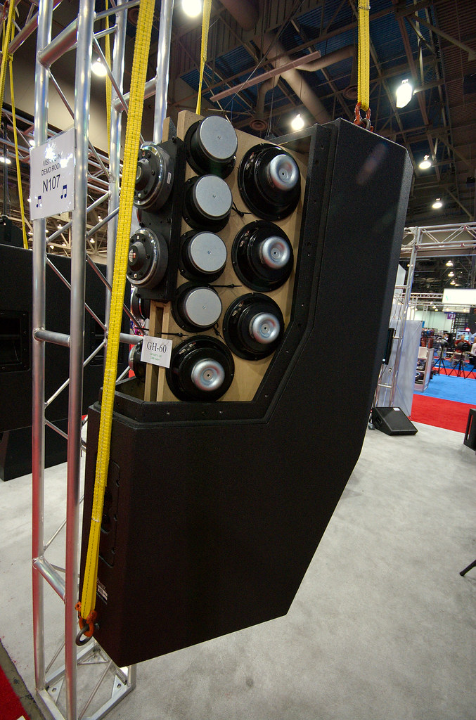
In the paraline patent, there's a picture of a paraline with a compression driver *and* four midranges mounted to the back plate.
You'd mentioned that you built one of these, but hadn't released it.
Did it function as expected?
The reason that I ask, is that it seems that a significant fraction of the midrange energy would arrive out-of-phase.
I understand that the dimensions of the paraline are so small, that the midrange wavelength will not expand until they exit the throat.
BUT
The midranges are still radiating in 360 degrees, so a significant fraction of the midrange energy will be delayed, as it basically 'bounces around' inside of the paraline.
I can see how this *wouldn't* be a problem for the compression driver, because the compression driver is mounted right in the center of the device. But it seems like it would be an issue for the mids, since they're mounted off axis.
To my eyes, it seems to be similar to the problem in the Synergy horn, where a notch appears at a predictable frequency because their energy reflects off the throat. But the difference in the paraline is that the distance is much further, because the width of the paraline is acoustically significant.
This would probably make more sense if I included a diagram, but I hope that was clear enough. I like the idea of having five drivers inside of the paraline, but I can't see how it would work.
Earl,
The definition of "tenable": “Capable of being maintained in argument; rationally defensible: a tenable theory.”
What rationally defensible device has an output with ALL rays that are the result of interactions near the source?
Art
Opps, meant "untenable", well really "questionable" or "doubtful".
In other words, tenuousOpps, meant "untenable", well really "questionable" or "doubtful".
.So what "questionable" device are you writing about that has an output with ALL rays that are the result of interactions near the source?
Art
Got tongue-tied!
Most of the drawings shown earlier in this thread had a device placed very close to the sources and used rays to show the effect of these devices. Very questionable technique that. (So I guess that I meant that the analysis technique was "tenuous" not the device.)
Most of the drawings shown earlier in this thread had a device placed very close to the sources and used rays to show the effect of these devices. Very questionable technique that. (So I guess that I meant that the analysis technique was "tenuous" not the device.)
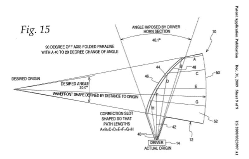
As noted in the first post, the 'neat' thing about these inventions is that they give you directivity control that's similar to a long deep horn, but without the brutal space requirements. For instance, one of the Paraline devices has a depth of about an inch, and claims to have the directivity of a horn which is over a meter long. (According to the marketing literature.)
The way that this is achieved is by using a clever reflector. Basically the driver faces upward, and the sound is reflected ninety degrees. The pic above, from the paraline patent, illustrates how this works.
If I'm not mistaken, the same math can be used to build your own S.A.W. lens.
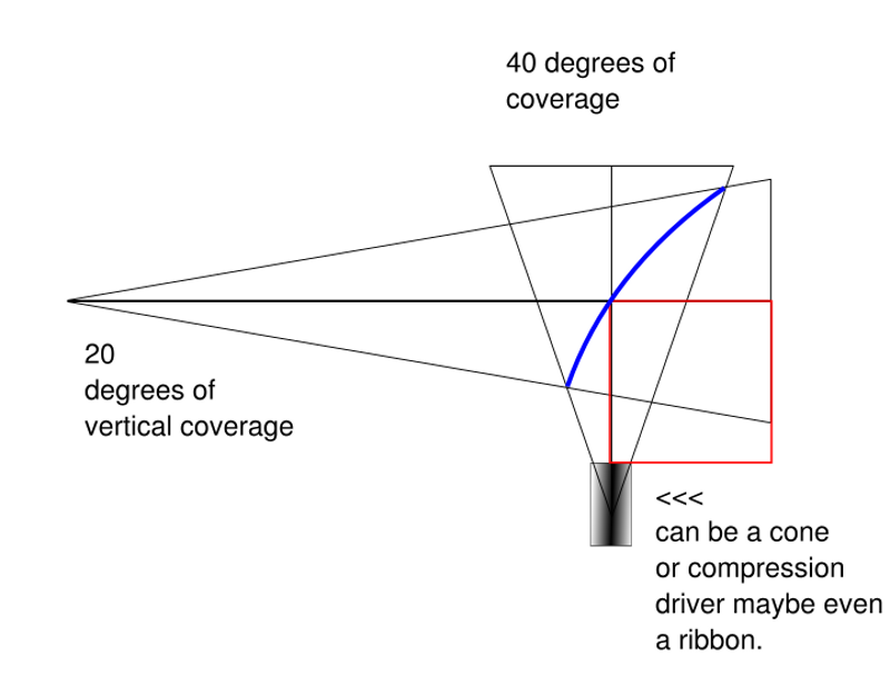
I took a stab at modeling one of these in Xara, using the dimensions from the patent.
An externally hosted image should be here but it was not working when we last tested it.
An externally hosted image should be here but it was not working when we last tested it.
This is a bit random, but Tupac Shakur was 'resurrected' via 3D animation, a trio of projectors, and a pile of mylar last week:
2PAC ALIVE Feat Snoop Dogg at COACHELLA 2012 (Tupac Hologram) - YouTube
Tupac coachella 2012 - YouTube
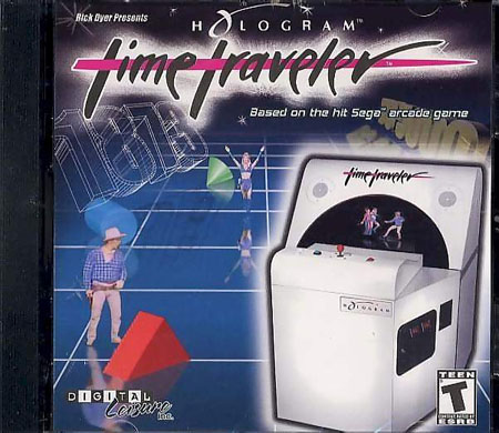
I used to work in a video arcade when I was in college, and we had a machine that pulled off a similar trick. It's called "Time Traveler", and it was made by Sega:
Sega's "Hologram" TimeTraveler coin-op Press Coverage (circa 1991) - YouTube
The thing that's amusing about it - is that it's basically very similar to the acoustic reflector that's detailed in this thread. I took our Time Traveller machine apart, and was amused to find that the 'hologram' trick is very very simple. There's a Sony Trinitron television mounted in the based of the cabinet, and a black mylar spherical mirror is set in front of the television set.
An externally hosted image should be here but it was not working when we last tested it.
An externally hosted image should be here but it was not working when we last tested it.
some pics of the mirror and the game it came from
To complete the illusion, a layer of smoked glass is placed on top of the whole contraption. The smoked glass obscures both the television set and the spherical mirror. So all you see is the reflected light from the spherical mirror, and the 'holographic' image seems to float above the glass. (Check out the youtube video to see what I'm talking about.)
If I'm not mistaken, it's the same technology used in the Coachella video. The main difference is that they used three 1080P projectors instead of a television set.
I'm too lazy to draw up a diagram, but it's the same idea as the paraline. In the Sega game, the TV and the mirror are underneath the glass, and the image is projected vertically. (The light from the TV is bent 90 degrees, and goes straight up.)
In the Coachella 'hologram', I'd guess they did the same thing. The only difference is the scale. You'd need a concert stage that's transparent, and the projectors are *under* the stage, which then bend the light at a 90 degree angle to create the hologram, which shoots straight up.
It's a neat trick as long as the content of the is two dimensional, such as fighting games or climbing games. (Street Fighter II, Mario Bros, etc.)
Or someone pacing the stage, like in the Coachella stunt.
If the content is 3D I imagine the wavebending would get distracting.
And again, if you look at the schematic of the paraline from the patent, the idea is the same. Instead of a speaker as the source, it's a television set.
Ok, so it's like this age old "mirror bowl" trick where you put the bowl under a glass table and put a quarter in the bottom of it and see if people try to grab it? This bowl has a plastic pig toy in it.
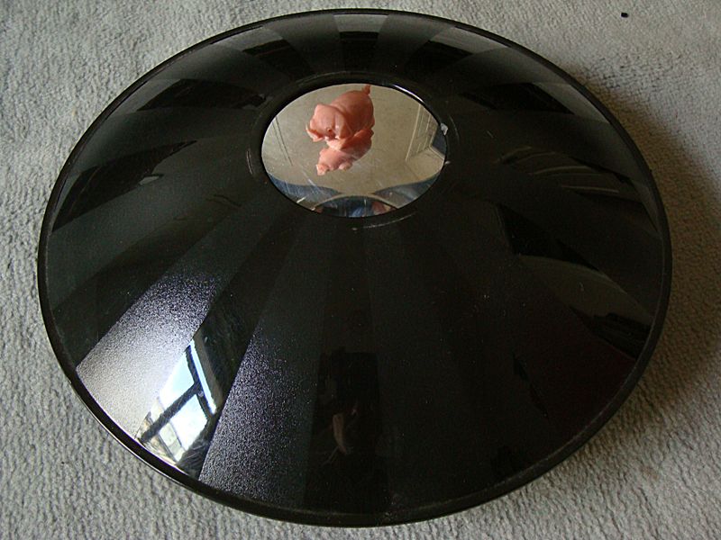
Sorry for huge image. I don't like the term hologram that applies to any 2d image that appears to be floating in space. I had always thought true holograms were fully 3d in appearance. It seams that technology has not advanced much with holograms Sure, he's floating in space, but he is not fully 3d as far as I can tell. He's a flat 2-pac floating in space, and all viewers see the same image regardless of viewing angle (like looking at a tv and walking around, the image always looks at you, but eyes don't move). I miss real holigrams that changed view depending on angle viewed from.
I am curious how a paraline waveguide would effect the sound if you walked around it and listened from different angles. Mr. Geddes describes an far from perfect reflection based on non linear waves... I understand it... So I am imagining the image and sound would vary depending on where you are listening from. Sound like something you don't want...
Sorry for huge image. I don't like the term hologram that applies to any 2d image that appears to be floating in space. I had always thought true holograms were fully 3d in appearance. It seams that technology has not advanced much with holograms
Sure, he's floating in space, but he is not fully 3d as far as I can tell. He's a flat 2-pac floating in space, and all viewers see the same image regardless of viewing angle (like looking at a tv and walking around, the image always looks at you, but eyes don't move). I miss real holigrams that changed view depending on angle viewed from.I am curious how a paraline waveguide would effect the sound if you walked around it and listened from different angles. Mr. Geddes describes an far from perfect reflection based on non linear waves... I understand it... So I am imagining the image and sound would vary depending on where you are listening from. Sound like something you don't want...
I have an idea, let's call this "sonic holography!"
(oh wait, that's taken)
Here's the reflector from the Paraline patent
Here's a neat side view of the Sega hologram device. At first it may look different, but just rotate the picture 90 degrees to the right, and you'll see it's the same thing
Here's a great picture illustrating the Sega device, which illustrates what's going on way better than I can do.
I believe the Coachella stunt is the same trick, just scaled to a much much larger size.
One thing I didn't realize with the Sega device, is that there are *two* mirrors. Basically the television set projects the light away from the player, the spherical mirror inside the cabinet bends the light up, and then the spherical mirror outside of the cabinet bends it *again.*
Neat!
(oh wait, that's taken)
Here's the reflector from the Paraline patent
An externally hosted image should be here but it was not working when we last tested it.
Here's a neat side view of the Sega hologram device. At first it may look different, but just rotate the picture 90 degrees to the right, and you'll see it's the same thing
An externally hosted image should be here but it was not working when we last tested it.
Here's a great picture illustrating the Sega device, which illustrates what's going on way better than I can do.
I believe the Coachella stunt is the same trick, just scaled to a much much larger size.
An externally hosted image should be here but it was not working when we last tested it.
One thing I didn't realize with the Sega device, is that there are *two* mirrors. Basically the television set projects the light away from the player, the spherical mirror inside the cabinet bends the light up, and then the spherical mirror outside of the cabinet bends it *again.*
Neat!
Thanks for taking the time to share your thoughts on acoustic lenses!
A few questions:
- Did anyone make more progress on the algorithm for calculating the acoustic lens dimensions? Step 2 assumed 40 degrees and Step 4 15cm.
- Other than being patented, what are the cons of acoustic lenses - assuming one uses the appropriate algorithm to derive their geometry?
Cheers
Ps. The reason I'm asking is that I'm trying to decide which design pattern to use for a pair of active floor standing full range speakers. I'm basically on square one, evaluating the pros and cons with
- Beolab 5
- Linkwitz Orion
- More traditional 3 or 4 way cabinets
In airline simulators, these are called collimated displays.I have an idea, let's call this "sonic holography!"
(oh wait, that's taken)
Here's the reflector from the Paraline patent
An externally hosted image should be here but it was not working when we last tested it.
Here's a neat side view of the Sega hologram device. At first it may look different, but just rotate the picture 90 degrees to the right, and you'll see it's the same thing
An externally hosted image should be here but it was not working when we last tested it.
Here's a great picture illustrating the Sega device, which illustrates what's going on way better than I can do.
I believe the Coachella stunt is the same trick, just scaled to a much much larger size.
An externally hosted image should be here but it was not working when we last tested it.
One thing I didn't realize with the Sega device, is that there are *two* mirrors. Basically the television set projects the light away from the player, the spherical mirror inside the cabinet bends the light up, and then the spherical mirror outside of the cabinet bends it *again.*
Neat!
<snip>
How large the reflector is acoustically governs how it reflects until it is very large where it acts more like a mirror (as in Earls Fig2) or it is very small like a small fraction of a wavelength where the pressure goes around the object.. The Paraline thing mentioned here uses path length only, no reflections and bends in the plane where the dimension is a fraction of a wavelength at 20Khz.
<snip>
Best
Tom Danley
I have a couple observations about the Paraline, curious if you might comment or confirm them.
#1 - The cone shaped 'nipple' inside of the Paraline is used to reduce the exit volume of the compression driver. My hypothesis is that this is because the area of the Paraline where the compression driver mounts is so small, if you didn't reduce the volume in the throat you'd get the equivalent of a horn that goes from a large volume to a small volume. So the 'nipple' is used to modify the volume at the throat, so that the volume of the Paraline expands all the way down the line.
#2 - I am too lazy to re-read the patent, but iirc the patent indicated that the prototype was 1/2" tall inside the line. But based on what you've posted here, it looks like we want a height of 0.22".
Here's why:
According to your post, to operate to 20000khz we want the height of the Paraline to be approximately 1/3 wavelength at 20khz. That's 0.57cm, or 0.22".
If we subdivide the Paraline into a series of concentric rings, we see a pretty nice match for the VTC horn.
For instance, "ring 0" is the exit of the compression driver. It's a 1" compression driver, so it has an area of 5.07cm. As noted above, I think that 'nipple' contraption is there to reduce the volume of the compression driver exit.
The next ring, I'll call it "ring 1" has an area of 9.65cm^2 if the height of the Paraline is 0.64cm, or 0.25".
The ring after that, I'll call it "ring 2" has an area of 16.08cm^2, again with a height of 0.64cm.
Note that the area calculations above are based on my assumption that the line in the Paraline is 0.25" in height. It seems like it needs to be, if we want it to play to 18khz. Either that, or it's 1/2" tall and it only works properly to 9000hz.
If anyone is following me here, what I'm getting at is that the expansion rate of the horn is nice and constant. That's very important, because it prevents reflections back down the horn. Basically the Paraline can be modeled like any ol' horn, you could even use Hornresp. It's just a very clever folding scheme.
So the Paraline seems to do a couple things:
#1 - If my 'hunch' is right, the 'line' inside the Paraline is 0.25" tall. That very shallow height gives us high frequency response up to 18000hz. (speed of sound / height / 3).
#2 - Because the wavefront expands radially, all the pathlengths are equal, or very close to it. This eliminates / minimizes comb filtering.
Last edited:
I guess I'll take a stab at reverse engineering this thing.
Based on the math that Tom posted, my hypothesis is that the line in the Paraline is 0.25" tall. Next, we need to figure out the dimensions of the 'eye' in the Paraline.
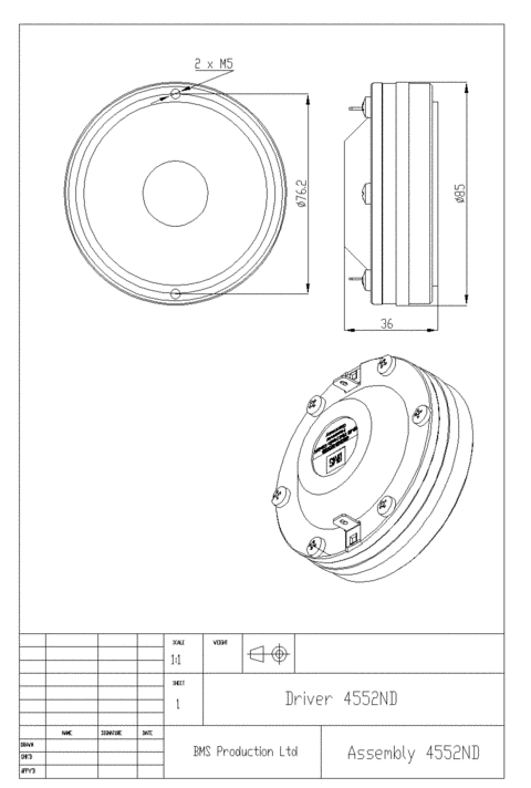
From the pictures at VTC, I believe they've opted for the neodymium version of Danley's favorite compression driver. So instead of the BMS 4550, they're using the 4552ND.
Once we know the compression driver, we have a fairly good idea of the 'eye' dimensions, because the 4552ND is 8.5cm in diameter.
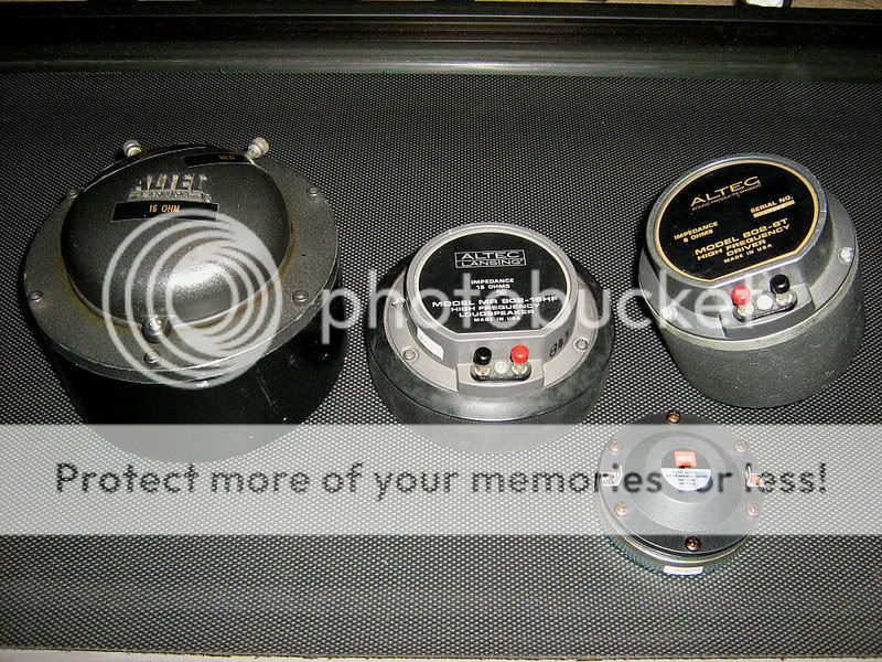
I think it's hard to appreciate how *small* this thing is! When I first looked at the pictures, I'd assumed that the compression driver was the size of a B&C DE250. But it's much smaller. In fact, the foot print of a single Paraline isn't much larger than a compact disc!
I think this makes sense in the context of how it's used. If you're using two or eight or sixty four compression drivers, neodymium is the way to go.
Based on the math that Tom posted, my hypothesis is that the line in the Paraline is 0.25" tall. Next, we need to figure out the dimensions of the 'eye' in the Paraline.
From the pictures at VTC, I believe they've opted for the neodymium version of Danley's favorite compression driver. So instead of the BMS 4550, they're using the 4552ND.
Once we know the compression driver, we have a fairly good idea of the 'eye' dimensions, because the 4552ND is 8.5cm in diameter.
I think it's hard to appreciate how *small* this thing is! When I first looked at the pictures, I'd assumed that the compression driver was the size of a B&C DE250. But it's much smaller. In fact, the foot print of a single Paraline isn't much larger than a compact disc!
I think this makes sense in the context of how it's used. If you're using two or eight or sixty four compression drivers, neodymium is the way to go.
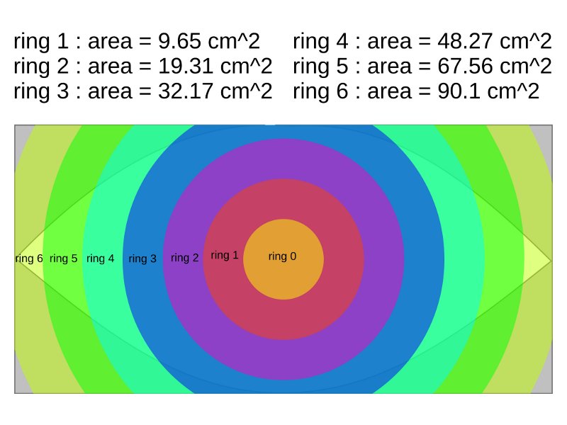
Based on my hypothesis about the internal height, here's an illustration of the 'rings' in the Paraline.
The reason that i'm 'digitizing' the Paraline into a series of concentric rings is that it allows us to simulate the Paraline in Akabak or Hornresp.
Ring 0, the central ring, is our compression driver.
Each successive ring grows larger and larger. The expansion rate is fairly constant, similar to a conical horn. This may be one of the reasons that the Paraline mates up nicely with a conical horn.
A few observations:
- The area of each ring in my illustration is based on an internal height of 0.25". This assumption is based on Tom's comment that the upper limit of the device is approximately 1/3 wavelength of that height. A height of 0.25" gives us an upper limit of 18000hz.
- You should be able to take my numbers and scale them. For instance, if you want an upper limit of 1125hz you could use an internal height of 4". The volume of each ring would then be 16x higher. These types of paralines may be useful for midrange or bass horns. While a bass Paraline may sound odd, it could be a novel construction technique for putting a basshorn under a bed, or behind a television set. (since it's very very flat.)
[*]Since the sound wave is expanding radially, when you model this in Akabak, each ring segment is 2.54cm in length.
If anyone has any comments or suggestions on this model of the Paraline, please post 'em.
Last edited:
At very high frequencies, sound waves act like light waves reflecting off a mirror. The parabolic cone shape in the throat of the Paraline directs the HF waves properly from the center of the coupler outward.#1 - The cone shaped 'nipple' inside of the Paraline is used to reduce the exit volume of the compression driver.
#2 - I am too lazy to re-read the patent, but iirc the patent indicated that the prototype was 1/2" tall inside the line. But based on what you've posted here, it looks like we want a height of 0.22".
Here's why:
According to your post, to operate to 20000khz we want the height of the Paraline to be approximately 1/3 wavelength at 20khz. That's 0.57cm, or 0.22".
Note that the area calculations above are based on my assumption that the line in the Paraline is 0.25" in height. It seems like it needs to be, if we want it to play to 18khz. Either that, or it's 1/2" tall and it only works properly to 9000hz.
The coupler maintains (around) a 1/4" width throughout, allowing for extended HF.
The Paraline devices I built, which are about 9.75" tall, using a 1.4" entrance, use 3 layers of 1/4" plywood and have HF response out to the extent of the EV DH1HT driver used, about 16,000 Hz.
Art
Now that we have the dimensions of our Paraline, let's figure out how to make it a Synergy horn. (It's right there in the patent, no reason not to right?)
According to JLH, "The compression driver’s crossover point dictates where the mids should tap into the horn. Example -If the compression driver’s crossover is 1500Hz, then the mids need to tap into the horn where the cross-sectional area is 41.54 cm2 or LARGER. It’s not about just trying to get the mids as close to the compression driver as possible. Because the compression driver is low passed at 1500Hz, the cross-sectional area where the circumference is equal to 1 wave length – any area larger than this becomes acoustically invisible to the compression driver. This is because the compression driver is cutoff at 1500Hz – thus its output cannot create acoustical pressure against the horn walls when the cross-sectional area is larger than 41.54 cm2. This pretty much removes the effects of the mid entry ports on the compression driver’s frequency response." *
I'm not 100% sure how this would work in a Paraline.
The Paraline expands at a slower rate than a typical Unity/Synergy horn. This creates a couple of challenges. If you place the midrange holes too close to the compression driver than the compression driver 'sees' the midrange holes. But if you place them too far away, a reflection off the throat creates a deep null in the midrange response.
And, obviously, this is completely complicated by the fact that this isn't a conventional horn.
Personally, I am inclined to believe that the effects of reflection will be minimal, because the dimensions inside the Paraline are so small, the wavefront can't even expand until it exits the Paraline.
For instance, with a height of 1/4", any waveforms below 13406hz can't even expand inside of the Paraline. (As I understand it, the air molecules excited by the loudspeaker diaphragm act like water in a pipe below 13406hz, and waveforms expand on the OTHER side of the Paraline, the side that mates with the rest of the horn.)
Here's the formula for this behavior:
It's ( speed of sound / dimensions of duct / 4 )
or ( 34000 cm per sec / 0.635cm / 4 )
= 13,406hz
Keep in mind that pathlength and phase still apply here. Even though the frequencies don't *expand* until they exit the Paraline, they're still delayed by pathlength.
That's the reason that radial expansion is so important here; it keeps everything in phase. If pathlength didn't matter, than we could use a plain ol piece of PVC pipe instead of a Paraline.
* Audio Psychosis • View topic - Under Dash Horn Alternative
Last edited:
After a few hours tinkering yesterday, I haven't been able to figure out a way to put the midranges inside the Paraline successfully.
So I am inclined to do what Danley is doing, and put the midranges OUTSIDE of the Paraline.
Here's a few reasons I couldn't get the midranges inside:
Basically, to model a horn using a Paraline, I think we need to treat each section as if they're stacked on top of each other. A horn on top of a horn on top of a horn. So the top horn is the Paraline, the next horn is the midrange section, and then the next is the low frequency section. The mouth of the Paraline is the throat of the midrange section, the mouth of the midrange section is the throat of the low frequency section.
The downside to putting the midranges outside of the Paraline is delay. Due to the pathlength in the compression driver and the Paraline, the midranges may need to be about 1/2 to 3/4 of a millisecond behind the compression driver.
The big question then, is whether this can be achieved via physical means, or whether this box needs a digital delay on the midranges.
So I am inclined to do what Danley is doing, and put the midranges OUTSIDE of the Paraline.
Here's a few reasons I couldn't get the midranges inside:
- In a horn with an offset midrange, like a Unity or a Synergy, there's a reflection that occurs from the midrange energy going towards the throat. But I can't see any way to simulate this with Hornresp. (IE, the Paraline is a horn, but hornresp doesn't seem to be capable of analyzing it fully, as Hornresp isn't aware that the dimensions are so odd. I believe Hornresp treats horns as if their cross section is round. While the Paraline *is* round-ish, the wave expands radially, not axially.)
Also, it seems to me the strongest reflection wouldn't be from the throat of the compression driver, it would be from the opposite side of the Paraline. - If you put the midranges OUTSIDE of the Paraline, like Danley does, the theory says that you'll get a reflection of the horn throat. BUT I think this would actually be less serious than in a conventional Unity or Synergy horn for two reasons. First, we can 'butt' the midranges right up against the throat. So that minimizes the reflection problem by driving it up high in frequency. This isn't practical in a Unity or Synergy horn because the throat is so small on them. But on a Genesis or Jericho horn the throat is much larger, due to the use of a Paraline or a Layered Combiner.
The second reason that the reflection in a Genesis or Jericho would be less serious is that the Paraline / Layered Combiner forms a physical barrier to sound transmission... Basically the midrange energy would have a very difficult time getting to the diaphragm of the compression driver because the Paraline/LC forms a barrier that all but prevents that.
Basically, to model a horn using a Paraline, I think we need to treat each section as if they're stacked on top of each other. A horn on top of a horn on top of a horn. So the top horn is the Paraline, the next horn is the midrange section, and then the next is the low frequency section. The mouth of the Paraline is the throat of the midrange section, the mouth of the midrange section is the throat of the low frequency section.
The downside to putting the midranges outside of the Paraline is delay. Due to the pathlength in the compression driver and the Paraline, the midranges may need to be about 1/2 to 3/4 of a millisecond behind the compression driver.
The big question then, is whether this can be achieved via physical means, or whether this box needs a digital delay on the midranges.
Last edited:
- Status
- This old topic is closed. If you want to reopen this topic, contact a moderator using the "Report Post" button.
- Home
- Loudspeakers
- Multi-Way
- ~ Sunshine ~