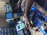
I didnt bother to do the cap test as the correspondence left me waiting for your valuable instructions, so what i did was install two of the fets and even retried the ones that was heating up, fets are good, all the test you told me to do i removed the output inductor AFTER i removed the fets from the second page of this thread.
You are so correct Mr. Babin, all your tests and results were onkey. it is now i saw that the inductor when in the circuit the fets are overheating. I get output by GRN and the input inductor PAD (before the relay ofcourse).
What do i do now?
You are so correct Mr. Babin, all your tests and results were onkey. it is now i saw that the inductor when in the circuit the fets are overheating. I get output by GRN and the input inductor PAD (before the relay ofcourse).
What do i do now?
The owner told me other tech tried to fix but I would have thought it worked with that inductor, that one seems messed up in sorting of the legs and besides it doesn’t seems like the original one that made with the amp does it?
Attachments
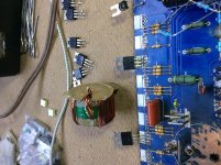
This may be what the original looked like:
sundown audio SAz-1000D
There may not be enough turns on the new inductor.
sundown audio SAz-1000D
There may not be enough turns on the new inductor.
No there isnt any heating without the inductor, i do not have signal genarator to induce a 80kHz signal on the input, but i have removed the 10k resistor and input audio (music) on the RCA and just from the inductor pad (from output fets drain legs) and it was still cool enough while it played.
**when the inductor is in, its not a gradually heating, its an immediate heating with a hissing sound (approx 1.8 seconds)
**when the inductor is in, its not a gradually heating, its an immediate heating with a hissing sound (approx 1.8 seconds)
I really dont know how to measure that signal, ive ground my Fluke 115 and put it on Hz setting and all i see is 50kHz and if i adjust the gain knob to max it gives me 52.63kHz max (flickering to music).
When i use the scope, it just shows me peak to peak square waves (flickering to music).
the inductor is still out the circuit**
When i use the scope, it just shows me peak to peak square waves (flickering to music).
the inductor is still out the circuit**
It sounds like it's working. The 80kHz was a generic value. 50K is low but that may change when a good inductor is installed.
Wind a wire (type and size not critical) with the number of turns seen in the other thread. You can leave the other windings in place. Does the inductor wound that way cause the previous problem?
Wind a wire (type and size not critical) with the number of turns seen in the other thread. You can leave the other windings in place. Does the inductor wound that way cause the previous problem?
I think im gonna go in town tomorrow to see if i can get one off my tech buddy shop, but i think i saw 28 turns on the other thread, i have a friend that repair speakers if i cant get one i will get some magnet wire of (near) that gauge and rewound it and let you know the outcome Mr. Babin.
Will the diameter of the core any thing to take into major consideration? or could i put one or two extra turns to compensate? (this current one they used seems a bit smaller).
Will the diameter of the core any thing to take into major consideration? or could i put one or two extra turns to compensate? (this current one they used seems a bit smaller).
Do you think this is a different core than was originally in the amp?
The diameter can make a difference but the core material is also important.
If you have some insulated hookup type wire, 22g or whatever you have, you can wind the cores to see if they are usable. The wire will have to be replaced with the proper magnet wire but it will prevent wasting time to get wire for cores that are not suitable.
I've confirm with the owner and yes it was swapped out as the original one was burnt and thats when the amp failed to operate properly after that, probably nothing wasnt even wrong with the audio driver card to begin with (hence me replacing those parts).
Ive found an old Earthquake PHD2 with same amount of turns and seems a match up physically from the pics of the thread you sent me, im going to try one of its inductor and let you know.
***could you confirm the output capacitors near the relay for me CE6, CE26 and CE29?
they are changed and having values 100v 10uf and are non-polarized (axial form factor). I was thinking it should be 250v but just want to be certain.
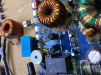
I can’t figure why when I removed all the caps from the output network after the inductor it plays fine but any one is install the inductor whistles and fets overheats?
This inductor is the closest match to the original which I do believe it should be able to work. Are all the caps bad?
***any cap installed there’s a 12v dc on the output.
No cap there’s 0.3v dc but when measured with ac setting I’m getting 14v to ground. Any suggestions, try newer caps (are they really non polar as the legend has the polarized mark)?
Attachments
- Status
- This old topic is closed. If you want to reopen this topic, contact a moderator using the "Report Post" button.
- Home
- General Interest
- Car Audio
- Sundown SAE-1000D