" ... Any opamp will do a good job due to the very low bandwidth requirements for the bass filter ..."
Now that's a nice looking response curve = 5 Htz to 150 Htz Low Pass Filter. I notice that you swapped the caps and resistors (again) ... assuming you are trying to "optimize" the curve and commonality of parts (10K and 20K being more readily available ... 22K = not). I also notice that you changed the pot to a 10K (??).
Any further suggestions in this regard would be welcome. I planned on using:
-Single sided board with a common star ground point.
-Single channel 8 pin DIP chips - 3 places.
-Provisions for multiple bypass caps = 47 uF electro & 100nF plastic, rail(s) to local ground
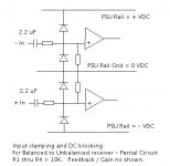
-Provisions for diode clamps on the inputs (limiting input to the rail voltage) ... & ...
-Provisions for a DC blocking cap of 2.2 uF (plastic) ... for my purposes, there would be a jumper instead of a cap. (see attached example below)
-Board mounted dual RCA connectors at input and single at output (I found some nice gold plated ones)
-Extra connect points for adding and changing caps to modify the curve within certain ranges.
-- R1 = 20K Ohms / film = 2 places
-- R2 = 10K Ohms / film = 1 place
-- RV = 10K to 100K Ohm Potentiameter / linear taper 5 or 10 turn = 1 place
-- C1 = 75 nF plastic = 1 place
-- C2 = 150 nF plastic = 1 place
(I'll be posting the PSU diagrams shortly.)
I don't know about everyone else, but my wife won't allow multiple, large sub woofer thumper boxes in the listening area = too many boxes, to much equipment, etc. ... thus the whole purpose of this excercise ... and I am somewhat of an opinion that too many sub woofers can muddy up the bass line ...
(I had thought of using these same boards for XLR balanced to coaxial unbalanced connection (a balanced to unbalanced line receiver) as well (attached below) ... but that may be asking for a whole lot of extra board holes ... not really wanting a "swiss army knife" type project.)
Now that's a nice looking response curve = 5 Htz to 150 Htz Low Pass Filter. I notice that you swapped the caps and resistors (again) ... assuming you are trying to "optimize" the curve and commonality of parts (10K and 20K being more readily available ... 22K = not). I also notice that you changed the pot to a 10K (??).
Any further suggestions in this regard would be welcome. I planned on using:
-Single sided board with a common star ground point.
-Single channel 8 pin DIP chips - 3 places.
-Provisions for multiple bypass caps = 47 uF electro & 100nF plastic, rail(s) to local ground
-Provisions for diode clamps on the inputs (limiting input to the rail voltage) ... & ...
-Provisions for a DC blocking cap of 2.2 uF (plastic) ... for my purposes, there would be a jumper instead of a cap. (see attached example below)
-Board mounted dual RCA connectors at input and single at output (I found some nice gold plated ones)
-Extra connect points for adding and changing caps to modify the curve within certain ranges.
-- R1 = 20K Ohms / film = 2 places
-- R2 = 10K Ohms / film = 1 place
-- RV = 10K to 100K Ohm Potentiameter / linear taper 5 or 10 turn = 1 place
-- C1 = 75 nF plastic = 1 place
-- C2 = 150 nF plastic = 1 place
(I'll be posting the PSU diagrams shortly.)
I don't know about everyone else, but my wife won't allow multiple, large sub woofer thumper boxes in the listening area = too many boxes, to much equipment, etc. ... thus the whole purpose of this excercise ... and I am somewhat of an opinion that too many sub woofers can muddy up the bass line ...
(I had thought of using these same boards for XLR balanced to coaxial unbalanced connection (a balanced to unbalanced line receiver) as well (attached below) ... but that may be asking for a whole lot of extra board holes ... not really wanting a "swiss army knife" type project.)
Attachments
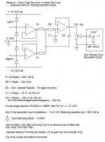
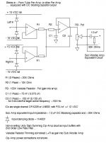
Update to diagram. Changes to resistors and capacitors values to reflect bjorno's work with the software analysis. Input to power rail clamping diodes added to protect the op-amps. +/- 15 VDC power connections to the op-amps not shown. All ground connections shown share a common connection in "star" configuration on this board. Note that a BottleHead tube pre-amp will be driving this circuit and it already has a DC blocking capacitor in its output, so the op-amps can "float" around their common ground without the need of any offset / DC balance circuit.
(I may use OPA 827 dual channel op-amps, three channels for the summing / low pass circuit and one attached ahead of the pot to drive a couple of LEDs to indicate any clipping and for threshold / "power on".)
Summing and filter board: http://www.diyaudio.com/forums/showthread.php?postid=1184532#post1184532
PSU board: http://www.diyaudio.com/forums/showthread.php?postid=1190803#post1190803
Attachments
Has anyone tried the above circuit? Seems perfect as I have a 12b4 pre with DC blocking caps at the output and I need to sum the stereo output without having any effect on the stereo out that is driving my bookshelf speakers.
I would then feed the mono out to a class D amp to drive a sub in my home hifi
I would then feed the mono out to a class D amp to drive a sub in my home hifi
I seem to remember that the inverting configuration is the preferred one for summing amplifiers?
Yes, it is.
Hi Y'all,
I hate to bring this up, but I seem to remember that the inverting configuration is the preferred one for summing amplifiers?
Regards,
You may very well be right about that. Inverting / summing op-amp configuration would be somewhat simpler.
(There are "purists" who prefer the non-inverting.)
My thoughts when reading this thread: Why not just use an inverting summer, then reverse the speaker leads. Or put a switch on the leads so you can try either polarity. (Sometimes the polarity needs to be reversed for the satellites, especially if not an integrated satellite and subwoofer system) My 2 cents...
- Status
- This old topic is closed. If you want to reopen this topic, contact a moderator using the "Report Post" button.
- Home
- Loudspeakers
- Subwoofers
- Summing Op-Amp circuit