All this talk about smoothing the mid entry port is unnecessary. If you place the mids correctly in regards to the crossover point, the entry ports will be acoustically invisible to the compression driver anyway. This works by having the mids tap in at a point where the circumference is longer than the lowest frequency the compression driver will reproduce. Since this point is acoustically large in regards to what the compression driver will play, its output will not “push” against the horn wall, or be able to acoustically “feel” the mid entry port.
Okay, that would work for me. It seems you are saying that @ the crossover freq of 1500 hz( which is a WL of 9") that would work but from previous posts Patrick(unless I've misread it) has mentioned the entry point should be @ 1/4 WL( which is 2.25"). Can we. Clarify a definite entry point?
Last edited:
JLH,
"f you place the mids correctly in regards to the crossover point, the entry ports will be acoustically invisible to the compression driver anyway. This works by having the mids tap in at a point where the circumference is longer than the lowest frequency the compression driver will reproduce. Since this point is acoustically large in regards to what the compression driver will play, its output will not “push” against the horn wall, or be able to acoustically “feel” the mid entry port."
Could you please point me to some reading material which explains this phenomenon, I can't get my head around why this is so.
thanks,
Kees
Okay, that would work for me. It seems you are saying that @ the crossover freq of 1500 hz( which is a WL of 9") that would work but from previous posts Patrick(unless I've misread it) has mentioned the entry point should be @ 1/4 WL( which is 2.25"). Can we. Clarify a definite entry point?
JLH is talking about the circumference at the entry point, not the distance to the CD entry. With a rectangular wave guide it might require a little testing, but I don't think it will vary much. In a rectangular Wg, the holes might even be less visible to the CD, as they are a little out away from the radiating pattern of the CD.
I'd measured my CD with the entry holes plugged on my Lambda Unity's (original design). Very little difference in frequency response. I've not measured impedance.
Sheldon
I’ll try to explain this as best as I can. I don’t know of any text that talks about it, it’s just one of the first principles of engineering.
Let’s set up an example with real numbers so you guys can follow along. We have a Unity/Synergy horn where the crossover between the compression driver and mids is 1.5KHz. We know that we must have the port entry within ¼ WL of the acoustic center of the compression driver at 1.5KHz. This means the mids can be as far away as about 5.7 cm. [342.7 M/S / (1500Hz*4) = 5.7 cm] In reality it can be a little bit more depending on how you want to use the acoustical cancelation notch. We now look at what the cross sectional area of our horn is at a distance of 5.7 cm. Let’s say the area is 41.5 cm^2. The circumference inside the horn at this point is 22.8 cm. Which is the WL of 1.5KHz. The thing I have found is if you set up your horn like this, you will end up with a bump, or a suck out at 1.5KHz. What you really need to do is leave a narrow gap between the mids and compression driver so the acoustic summation will result in a flat frequency response. Because of this let’s raise the compression driver’s crossover point to 1.65KHz. Now the WL of 1.65KHz is 20.77 cm. Since the lowest frequency our compression driver is reproducing is acoustically 10% smaller than the circumference of our horn at the mid port entries, it more or less beams instead of pressing against the horn walls. It does this because the horn has become acoustically too large for the 1.65KHz WL to “see” or “feel” the horn walls.
I explained this to another guy and in his mind he related it to the “sluts” he knew in college. He referenced the phrase “Oh, it’s like throwing a hotdog down a hallway ”. Nuff said.
All this talk about smoothing the mid entry port is unnecessary. If you place the mids correctly in regards to the crossover point, the entry ports will be acoustically invisible to the compression driver anyway. This works by having the mids tap in at a point where the circumference is longer than the lowest frequency the compression driver will reproduce. Since this point is acoustically large in regards to what the compression driver will play, its output will not “push” against the horn wall, or be able to acoustically “feel” the mid entry port.
If I understand you correctly, you are saying that moving the midrange entry holes to a point in the horn where the circumference is large minimizes their effect on frequency response, because the wavelength of sound is so much larger than the size of the holes. For instance, let's say you have a crossover frequency of 1000hz. If you locate the midrange holes where the circumference of the horn is 13.5", the angle of the horn will constrain directivity to such a degree, the holes effect is minimized.
The key here, if I understand correctly, is that the horn is constraining the output of the compression driver, because the output from the compression driver is geometrically smaller than the dimensions of the horn. IE, we wouldn't want to put the holes close to the compression driver, because the horn cannot control the directivity (because it's too small at that point.) Conversely, the output of the midranges is much larger, and the horn cannot control the directivity of their output. But the size of the holes is so small when compared to the wavelengths that the midranges are producing, that the holes are "invisible" to the midrange driver. Basically the requirements for the midrange and the tweeter are different, and we want the holes in a location where there's equilibrium between the two requirements. Move the holes too close to the compression driver and you screw up the high frequency output, because the horn can't constrain them.
One part that I don't get about this is that I would expect that the important variable would be the *diameter* of the horn, not the circumference. For instance, as I understand it, you would need a mouth of 13.5" to constrain the directivity of 1000hz. Based on that math, you'd need to locate the holes 14.48" from the throat in a fifty degree horn(!)
Synergy Horn Patent.

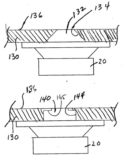
Conical holes. Don't do this. Doesn't work.
A combination of the slot from Yorkville, and the frustrum from Danley Sound Labs. Works well.
Some thoughts from my experiments...
- You can learn a lot from the synergy horn patent. I think John (JLH) has a much better grasp on what's going on in that patent than I do.
- The top pic above shows the holes from the synergy horn, which uses a frustrum instead of a simple hole
- While it's not obvious, there is no reason that the port has to be simple. The tuning frequency is based on the length and the area of the port. That's why a frustrum is a clever solution. It maintains the large area necessary to keep velocity down, while minimizing the size of the hole on one one side.
- You could also reverse the frustrum, and get a cone, but that doesn't work well at all. I tried
 It basically maximizes the discontinuity in the horn, which is the last thing you want.
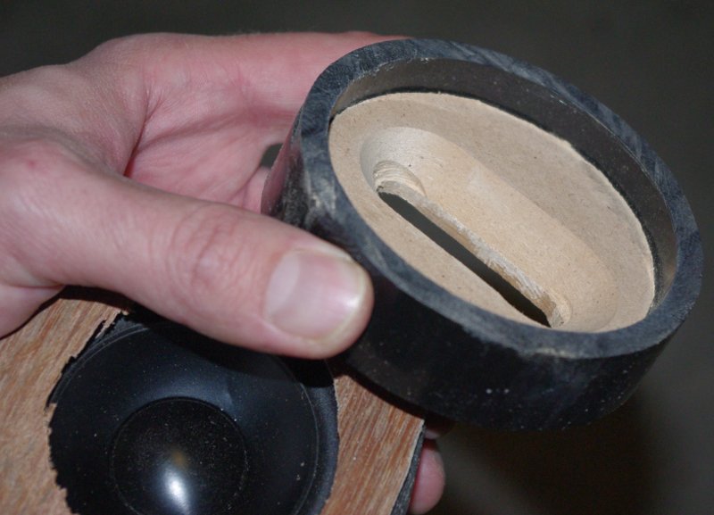
 - You need a surprisingly big hole to get good response. The second pic above was from an experiment where I tried using multiple small holes. The volume of the holes was too small - I needed big holes to get good response. Of course, reducing cones size reduces hole size. That's why I've had such good results with the lowly Tang Band W2 woofers (2" in diameter.)
- Probably the best results that I found were using a combination of the "slot" that Yorkville uses, along with the frustrum that Danley Sound Lab uses. The frustrum offers the advantage of large port volume, which improves the efficiency and response shape of the midranges. And the slot port seems to minimize the effect on the compression driver, simply because the area of the port is spread out. (IE, you'd expect a moderate depression in output, instead of a sharp dip. Just geometry.)
Last edited:
JLH is talking about the circumference at the entry point, not the distance to the CD entry. With a rectangular wave guide it might require a little testing, but I don't think it will vary much. In a rectangular Wg, the holes might even be less visible to the CD, as they are a little out away from the radiating pattern of the CD.
I'd measured my CD with the entry holes plugged on my Lambda Unity's (original design). Very little difference in frequency response. I've not measured impedance.
Sheldon
Interesting. Another reason to put the midrange holes in the corners, where the edges of the pyramid meet. I'd thought that the only advantage was that it reduces the discontinuity between the holes and the horn walls, hadn't considered that it also makes them more "invisible."
I may have to reconsider my plans on using a elliptical waveguide.
Okay, that would work for me. It seems you are saying that @ the crossover freq of 1500 hz( which is a WL of 9") that would work but from previous posts Patrick(unless I've misread it) has mentioned the entry point should be @ 1/4 WL( which is 2.25"). Can we. Clarify a definite entry point?
If in doubt, listen to John
A lot of my experiments have been trial and error, and my first Unity was riddled with mistakes.
Also, JLH, Sheerin, and I are all named John, just to confuse things further. (Patrick Bateman is a pseudonym. Get it? I'm "crazy about audio")
A lot of my experiments have been trial and error, and my first Unity was riddled with mistakes.
Yeah, but it sure did make for a really cool avatar when you doused it with gasoline.
Yeah, but it sure did make for a really cool avatar when you doused it with gasoline.
That was Danley's Unity
When he set it on fire I knew I had to use his pic for my first Unity project
Sorry guys,i lost my blackberry in the lake and haven't gotten to my PC as soon as i wanted to.
So JLH, the high frequency driver loses efficiency when it begins to beam? ASSuming it is not loaded by the horn below those frequencies, my thoughts are yes?! so if I get you correctly then I should widen the horn flare more than my crossover point dictates, if even by a few degrees and this will help any flare related interference.
I have seen those slots in a professional line array product ,I think JBL or something to that effect.
What are your thoughts on using a slot, considering the slot will span a good portion of the HF drivers wavelength so that the sound eminating from the closest point to the HF driver will be in step +/- but the sound further along the slot will be progressively delayed as it eminates???
I'm still thinking along the lines of a slot for an 8" driver, which will be wider and longer.
Last edited:
No, it doesn't have anything to do with efficiency. It’s about the physical length of the frequencies at play. You first select the coverage angles of your horn, and then you fit the drivers and crossovers to operate under the Unity/Synergy principles. Slots work just fine when placed at the correct distance from the compression driver. They barely have a measurable effect.
Interesting discovery, (perhaps not for the horn experts). If you increase the BL on the Misco or Pyle drivers and reduce the mass, the top end efficiency comes right up. The reason for the droop appears to be that both are less than ideal. If you keep reducing the mass and increasing the magnet strength you reach a point where the horn sims ruler flat. I don't know how accurate these sims are, but recently I had a chance to measure a Unity horn with the misco mid. Beautiful response, ruler flat.
Well, I can now say the Pyle PDMR5 works quite well as a Synergy/Unity style bandpass.
Sim vs measured:
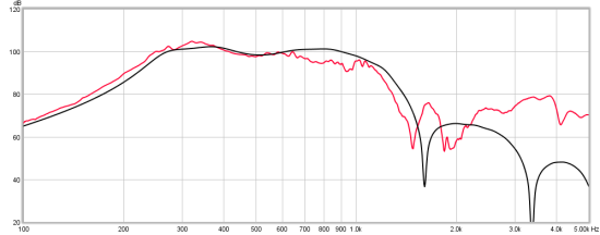
It did need a notch filter:
Red Spade Audio: Synergy horn - simulations vs measurements
Sim vs measured:
It did need a notch filter:
Red Spade Audio: Synergy horn - simulations vs measurements
This is a prototype, so I started simple with a 60 degree conical that is 500 x 500mm at the mouth (internal). Holes are 18mm cut into 18mm thick MDF. No kick out at mouth of the horn, just a 13mm roundover on the internal edge. The holes are 86mm from the exit tube along the axial length. Everything made as simple as it could be so that I could compare to the sim first then go through some trial and error. I was too impatient to learn Akabak, wanted to start cutting MDF!
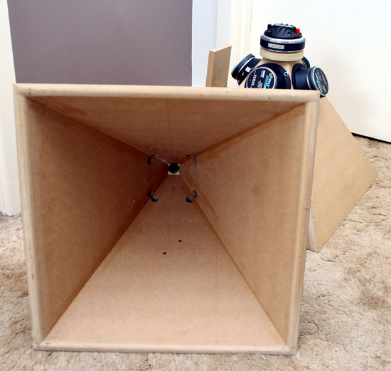
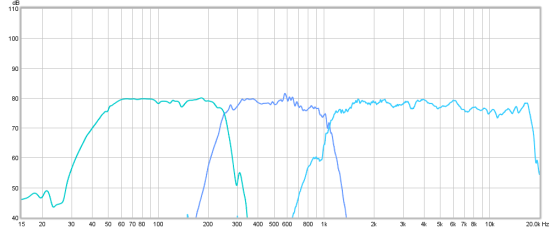
The CD response is smoother than my 6" oblate spheroid. All I needed was some shelving to flatten it out. The holes can't be doing too much to the HF response.
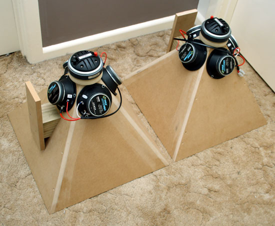
I found myself putting in the foam pretty quickly. I normally listen to my "Miniwaves" which are a cheap vifa driver with a 6" oblate spheroid and DE250. Then I built my surrounds with B&C 8PS21, much better midrange, still using same waveguide temporarily.
I prefer the sound stage of the waveguide speakers with 90 degrees. The Synergy has incredible sensitivity - you have to try it to appreciate what 102 db does! But I think to work for me, I'm going to have to get some wider dispersion. My impression is similar to what you posted about Unity vs Summa. I like the sensitivity and clarity and detail of the horn mids, but I'll probably get some more mids and put 6 on a 60 x 90. I want to get dispersion as wide as possible, but also extension as low as possible.
At this point I wish I did have Akabak worked out as it could probably help me figure things out better, and test out different ideas before building. Hornresp does seem to show some interesting things:
Red Spade Audio: Synergy horn - hornresp lessons
Playing with the front chamber volume and port length affects the top end roll off a great deal. I want to filter the top end acoustically as much as I can. The longer ports seem to cut off more rapidly.
As the coverage angle gets wider, the bottom end loading drops off. 60 x 90 with 6 drivers could be a workable compromise.
The CD response is smoother than my 6" oblate spheroid. All I needed was some shelving to flatten it out. The holes can't be doing too much to the HF response.
I found myself putting in the foam pretty quickly. I normally listen to my "Miniwaves" which are a cheap vifa driver with a 6" oblate spheroid and DE250. Then I built my surrounds with B&C 8PS21, much better midrange, still using same waveguide temporarily.
I prefer the sound stage of the waveguide speakers with 90 degrees. The Synergy has incredible sensitivity - you have to try it to appreciate what 102 db does! But I think to work for me, I'm going to have to get some wider dispersion. My impression is similar to what you posted about Unity vs Summa. I like the sensitivity and clarity and detail of the horn mids, but I'll probably get some more mids and put 6 on a 60 x 90. I want to get dispersion as wide as possible, but also extension as low as possible.
At this point I wish I did have Akabak worked out as it could probably help me figure things out better, and test out different ideas before building. Hornresp does seem to show some interesting things:
Red Spade Audio: Synergy horn - hornresp lessons
Playing with the front chamber volume and port length affects the top end roll off a great deal. I want to filter the top end acoustically as much as I can. The longer ports seem to cut off more rapidly.
As the coverage angle gets wider, the bottom end loading drops off. 60 x 90 with 6 drivers could be a workable compromise.
This is a prototype, so I started simple with a 60 degree conical that is 500 x 500mm at the mouth (internal). <snip>
Well I guess I need to take my own advice and start making some sawdust:
INTERNET ORDER DETAILS
-----------------------------------------------------------------------------------------------------------------------
QTY PartNumber Product Price Ext. Price
4 292-200 Pyle Pro PDMR5 5" Sealed Back Midrange $9.39 $37.56
1 300-750 Bash 300W Digital Subwoofer Amplifier $149.87 $149.87
1 FedEx Home Delivery $4.95 $4.95
-----------------------------------------------------------------------------------------------------------------------
Should have these in a few days. I already have a box of the Misco drivers but I've been reluctant to use them since I fear getting more could be a hassle.
I haven't decided what driver to use for a midbass. There's a dude on Diyma that's selling a car audio version of the B&C neodymium 15", the 15NW100. He's selling them for half of what they cost new, so I'll probably go that route if someone else doesn't buy them first.
here's the link - hard to go wrong at this price:
Pair of B&C 15NW100 woofers used - DIYMA.com - Scientific Car Audio - Truth in Sound Quality
- Home
- Loudspeakers
- Multi-Way
- Suitable midrange cone, for bandpass mid in Unity horn.