Ah, cool. Look forward to your results.
Thanks for the feedback; I'm honestly thinking of loading in the ~50 degree range until ~1500hz then branch out to 90 degree to get down to the 600 or so range (perhaps erroneously looking at it like a Keele flare). I think I'm depth limited to 24" along the wall, so about 27" along the primary axis, but that includes fitting drivers (one of the nicer things about those ribbons would be their shallow depth), so my low end loading will ultimately be packaging constrained.
Thanks for the feedback; I'm honestly thinking of loading in the ~50 degree range until ~1500hz then branch out to 90 degree to get down to the 600 or so range (perhaps erroneously looking at it like a Keele flare). I think I'm depth limited to 24" along the wall, so about 27" along the primary axis, but that includes fitting drivers (one of the nicer things about those ribbons would be their shallow depth), so my low end loading will ultimately be packaging constrained.
Yep, been using that + Hornresp (with the new functionality, it's pretty incredible) + a bit of Solidworks to see what I can fit. First entry will probably be foam board/cardboard before tooling up the heavy weaponry.
It's a great spreadsheet (plus your PDF going through the design choices), thanks for making that!
It's a great spreadsheet (plus your PDF going through the design choices), thanks for making that!
Since we are having so much luck with the SB Acoustics SB65WBAC25-4 as a mid and tweeter for the bookshelf horn thread, it probably would make a fine dedicated mid for band pass injection when used series parallel x 4. The basket is pretty compact - just needs a rear chamber. The benefit is that it can go pretty low with an fs of near 100Hz. When mounted near the throat of a synergy, I would not be surprised if you can go down to 350Hz before distortion is a problem. The other benefit is that it can go as high as you want to take it. If placed close enough to the tweeter, no reason it can't go up to 5kHz+ even (driver limited), but placement limited will depend on where the first cancellation dip is due to reflection from driver to tweeter. If a dome tweeter is used (as suggested by others and more recently by Onni in no comp driver synergy thread), the HF limit may be higher since you don't have that extra 1inch long transit from apex to comp driver diaphragm buried deep inside driver.
Last edited:
Offtopic but my nabure do like it to radiate me with a radar transmitter, I did measure 71 volts/meter or 13,3 watts on 8.5 gigahertz, that is reason of al the interference on equiptent and my headage of noisy ears.
not someting to be happy about as sensitive person, and so she try to get my out of my house, she do not like me, the only reason.
tomorrow I go take staps. big ones.
regards kees
not someting to be happy about as sensitive person, and so she try to get my out of my house, she do not like me, the only reason.
tomorrow I go take staps. big ones.
regards kees
Attachments
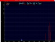
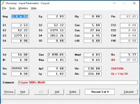
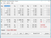
Experimenting with the Celestion TF0410MR but there appears to be a big difference between hornresp predictions and reality. I'm pretty sure the parameters I have for the driver are incorrect, could someone please confirm them.
Thanks.
Visaton do not include that, maybe ask them.
Experimenting with the Celestion TF0410MR but there appears to be a big difference between hornresp predictions and reality. I'm pretty sure the parameters I have for the driver are incorrect, could someone please confirm them.
Thanks.
If you think the parameters are incorrect and you have the driver, measure the driver's parameters yourself. That's the best way to do it. Honestly I would always measure the actual drivers I received to see what the actual parameters are. They will always be at least a little different from the published values due to manufacturing variation.
Original unity kit midrange
I just received the original midrange drivers from the early unity kit.
JC5RTF-B | Misco Speaker Company
I just received the original midrange drivers from the early unity kit.
JC5RTF-B | Misco Speaker Company
I know this thread is focussed on the midrange drivers of a synergy horn. But after reading (almost) all pages I'm generally wondering about the driver for the low frequency. I'm working on a 3 way synergy which needs to be a bit budget.
Celestion CDX1-1445 for hf
GRS 5SBM-8 5" for mid
And now I'm looking at this one for the low freq:
GRS 8SW-4 8"
The mid and low have 100Hz overlap... Not sure if that's a good choice...
Any suggestions?
Thanks!
Celestion CDX1-1445 for hf
GRS 5SBM-8 5" for mid
And now I'm looking at this one for the low freq:
GRS 8SW-4 8"
The mid and low have 100Hz overlap... Not sure if that's a good choice...
Any suggestions?
Thanks!
I'm still in middle of my build working out details, but here are the impressions I get from reading about synergies. YMMV
The Celestion is given a recommended crossover of 2,200 kHz, 12 dB/octave. That's pretty high for those 5" mids to hit. I think the biggest issue is getting them as close to the throat as possible, since you get a cancellation notch from the quarter wave distance from the port to the compression diaphragm. That said I'm pretty sure it can be done.
Overlap of any drivers is generally a good thing because it means you can make a more perfect crossover. You'd have to be more specific about how you're loading the drivers to show that you've actually got overlap. The problem I see with the GRS woofer is it's got a large VAS so you're gonna need large cabinets. Not a problem for home use but it's gonna be big for PA.
I think you might have difficulty getting a 5" mid close enough to use with the CDX1-1445. Depends on the horn it's on, though (wider angle will let a larger mid get closer to the tweeter throat). And what you're trying for in phase response -- if going for linear phase (without an FIR equalizer, that is), you'd need a very small midrange, like a 2" or so!
Due to the fact that this would be my first synergy build, I'm thinking of switching to a less difficult build. That's why I'm thinking of building something more like these:
http://www.diyaudio.com/forums/multi-way/195955-unity-horn-budget-drivers-active-x-over.html
At my school I can use a CNC mill so I'm working on a 3d model which I will produce using the mill. I think building a less complicated horn as a first timer is a good practice. (I have mostly build subs, ported, horns and tapped horns)
Jmorken is using Selenium D220Ti for HF but those aren't available so any recommendations on that?
I will probably start my own thread in the future, so I'll stop hijacking this thread!
Just ordered four of the Celestions from Blue Arran (as per link above) - they seem to have 20 or so in stock so get'em while they are hot!
Me too. Just ordered 8 out of the 14 they had in stock.

Downloaded and updated to the latest version of Hornresp but can't seem to bring up the Ap1/Lpt combo, no matter how many times I double click.
Oddly, I can only get these two sets of combinations, Ap1/LP and Ap/Lpt.
What am I missing?
Oddly, I can only get these two sets of combinations, Ap1/LP and Ap/Lpt.
What am I missing?
Attachments
I have another question. What starting value should be used to calculate the local flare rate for a 1" CD? Candidates are 2.53cm2, 3.226cm2 and 5.067cm2.
I found some conflicting info from JLH on the subject:
and
vs.
I found some conflicting info from JLH on the subject:
That's not correct unless you are using a compression driver that is smaller than 1". A 1" compression driver has a throat area of 5.067cm^2. [Regarding 2.53cm2 used in Bill's spreadsheet,] S1 is less than 5.067cm^2 because he is accounting for the internal structure of the compression driver. I'm not sure if he actually measured the acoustical path length, or made a physical measurement of the driver. The internal flare is of no concern. You want to know what your horn is doing. Start with 5.07cm^2 and perform the flare rate calculation based on the distance it takes to expand to 10.14cm^2.
and
You can't get a driver to deliver any significant output below the flare rate it is loaded to. For a 1” compression driver the starting area is 5.07cm^2.
vs.
I think you might have some miscalculations. When determining the flare rate in the throat of these conical horns, you have to start with a 0.7071" by 0.7071" throat because from corner to corner it is 1". You then sand out the throat to make it 1" in daimeter. The actual starting area for your calculation would be 3.226cm^2 and not 5.067cm^2. Try re-running your numbers with this in mind. You should see those flare rates drop to much lower numbers. I know on a 60 X 40 horn the flare rate the compression driver sees is around 1300Hz.
A few other conflicting pieces of info (IMHO) that I struggle a bit with:
and
First, I thought it was the local flare rate and not the cross-sectional area that determined at which frequency the horn stops loading the CD?
Second, I thought we are supposed to tap the mids in where the area is equal to or less than 64.91cm2?
IOW, like this:
... keeping in mind that the mids should not go too close to the throat:
Let’s use an example where we are crossing over a compression driver at 1200Hz. At this frequency the full wave length is about 28.56cm long. If we take this compression driver and load it into a conical horn, the horn will stop providing a load to the driver around where it expands to 64.91cm^2. Once you expand to beyond an area that is greater than one full wave length, the driver can no longer exert any pressure against the horn walls. To fully ensure you won’t get interference, you want to tap the mids in where the area is slightly larger than 64.91cm^2.
and
If the compression driver’s crossover is 1500Hz, then the mids need to tap into the horn where the cross-sectional area is 41.54 cm2 or LARGER. It’s not about just trying to get the mids as close to the compression driver as possible. Because the compression driver is low passed at 1500Hz, the cross-sectional area where the circumference is equal to 1 wave length – any area larger than this becomes acoustically invisible to the compression driver. This is because the compression driver is cutoff at 1500Hz – thus its output cannot create acoustical pressure against the horn walls when the cross-sectional area is larger than 41.54 cm2.
First, I thought it was the local flare rate and not the cross-sectional area that determined at which frequency the horn stops loading the CD?
Second, I thought we are supposed to tap the mids in where the area is equal to or less than 64.91cm2?
IOW, like this:
Find the flare rate that the compression driver sees, so you know how low it will be able to play. To avoid coloration and honk, you want the flare rate it sees to be lower than the crossover point. (e.g. If the compression driver’s local area flare rate is 1000Hz, then you want to highpass it at something like 1100Hz or 1200Hz.)
The cross sectional area dictates how high you will get high frequency loading from the horn. The area the mid taps into needs to have a circumference less than or equal to the wave length of highest frequency of interest. For 900Hz you want to tap into the horn where the area is approximately 115cm^2 and 146cm^2 for 800Hz.
... keeping in mind that the mids should not go too close to the throat:
One of the most common mistakes I see is tapping the mids into a throat area that is too small. This is what leads to the peaking right before the response falls off due to the 1/2 WL cancellation notch
If you move the midranges close to the throat, then you'll never get them to play low enough in frequency to meet up with the woofers. If the cross sectional area the midranges tap into is has a circumference equal to, or less than the lowest frequency played by the compression driver the ports will cause interference and frequency response abnormally.
Re-read the Synergy patent. There is no conflict in what I wrote. There are several hings that should occur to make a synergy horn work a described in the patent. However, if you run all the math on actual synergy horns, they don't meet all the "requirements" stated in the patent.
Downloaded and updated to the latest version of Hornresp but can't seem to bring up the Ap1/Lpt combo
Hi InOtIn,
A slight change was made to the port label names some time ago. The current names are as given in the Help file:
Ap - Vented rear chamber port cross-sectional area (sq cm).
Lpt - Vented rear chamber port tube length (cm).
Ap1 - Throat port or throat adaptor entry cross-sectional area (sq cm).
Lp - Throat chamber port or throat adaptor length (cm).
Kind regards,
David
Re-read the Synergy patent. There is no conflict in what I wrote. There are several hings that should occur to make a synergy horn work a described in the patent. However, if you run all the math on actual synergy horns, they don't meet all the "requirements" stated in the patent.
Thanks for replying and apologies if I'm being a bit thick - but I have read the patent a few times, as well as this and other synergy threads, and from what I've taken away so far is that the first of these statements, in relation to mid port location, is in accordance with the patent while the second statement seems to say the exact opposite of the first, no?
The area the mid taps into needs to have a circumference equal to or LESS than or equal to the wave length of highest frequency of interest.
If the compression driver’s crossover is 1500Hz, then the mids need to tap into the horn where the cross-sectional area is 41.54 cm2 or LARGER.
I'm a bit late to the Synergy game but I'm excited to dive straight in and get my feet wet - just need to get my facts straight first, so please bear with me while I'm trying to do so.
- Home
- Loudspeakers
- Multi-Way
- Suitable midrange cone, for bandpass mid in Unity horn.