A friend of mine had the same issue, no way to hook up the sub woofer. We both spent some time looking for an answer and I thought some might find it interesting:
There are 2.1 receivers on the market; the Harman Kardon has digital and optical inputs (that would be nice).
http://www.amazon.com/Harman-Kardon-HK-3490-Receiver/dp/B00198F89A/ref=sr_1_1?s=electronics&ie=UTF8&qid=1324296991&sr=1-1
http://www.amazon.com/Yamaha-R-S500BL-Natural-Stereo-Receiver/dp/B0044779GI/ref=sr_1_1?ie=UTF8&qid=1324297839&sr=8-1
There is also a Denon with HD radio, pretty expensive though.
Please excuse the interruption.
Yes, it is the same I suggested in my earlier post, but neatly drawn out. Just don't take 1/4 W resistors; use 1 W just to be on the safe side.
vac
Thanks, Vacuphile. It is the same as you suggested earlier. I just found it easier to reference the picture. Sorry for the lack of credit given.

@UV101... I hear what you are saying. I'm sort of a signal purist myself. But in this case it's not really that critical. My sub is only adding energy below 50Hz. It's there simply to reinforce what the main speakers are doing. So, I'm assuming, not SO critical for signal purity.
Also, adding a pair of high quality resistors that will, essentially, be seen by the amp as a couple more parts in the speaker Xover is likely to have far less of an impact than a buffer circuit and the quality of it's power supply. It's only real impact is in the overall impedance that the main amp sees. Which is why vacuphile specifies something larger than what the Linkwitz circuit shows. A 1k ohm resistor in parallel to the 4ohm load of the speaker has a smaller impact than a 50ohm resistor. (I know this is oversimplifying, but still.)
As it stands, my entire system has exactly two gain stages. Both of them in the main amp. I've adjusted my source to have the same maximum voltage as the input sensitivity of my main amp. My source also has a very nice buffer output, which is why it's output impedance is a very low 5ohm. With this i've abandoned an active preamp all together. What I have, instead, is basically the exact same circuit that Vacuphile has suggested, between my source and main amp, with the only difference being a variable resister at R2. This gives me my volume control without the added complexity of gain stages in a preamp. Also, there is still the problem of my sub amp having a lower input sensitivity compared to my main amp. I would still have to add a voltage gain stage of some sort in order to make it work right were I to take the signal before the main amp. This is why I figure I may as well use the gain stages in my existing main amp.
So, in my case, adding all of this to the output of the main amp is still the most pure way to go about it. When it really comes down to it, it's no different than what the likes of YG Acoustics, Evolution Acoustics, and Avantgarde (to name a few) are doing in their megabuck speakers. All of those designs take part of the signal from the main amp and split it off to run a separate internal amp for the woofer section of the speakers.
I'm doing the same thing, just in a more obvious way.
Thanks again all. I'll try it soon and report back how it went.
Last edited:
So I tried the voltage dividing circuit suggested by vacuphile. But I wasn't thinking straight to start off with. My amp is a parallel balanced design with a floating ground. So I altered it by putting 10K in series off each phase followed by the 1K in parallel. Works great with absolutely no perceivable degradation in sound from the main speakers.
Thanks to everyone for their input.
Thanks to everyone for their input.
10k in series with the signal followed by the 1k0 to signal return/ground will create a divide by 11 attenuator. i.e an 11Vac signal input becomes a 1Vac signal output. Roughly equivalent to -21dB.
The input impedance will be 11k when the next stage has a very high input impedance.
The output impedance is ~1k
I don't know what your "blacks and reds" are.
The input impedance will be 11k when the next stage has a very high input impedance.
The output impedance is ~1k
I don't know what your "blacks and reds" are.
I don't know what your "blacks and reds" are.
Blacks are let and right -, and reds are left and right +.
Sorry for my "noobness"
Blacks are let and right -, and reds are left and right +.
Sorry for my "noobness"
Surfed some more and found out that summing the signal is not a good idea. I guess I'll just give the sub signal from one channel. Will that be ok?
I think you have misunderstood what you found.Surfed some more and found out that summing the signal is not a good idea...............
Using a summing circuit (adder) is a standard way to ADD two signals together.
eg. a 2.1 music system is two stereo channels that are summed and filtered to create the third channel.
Similarly 5.1 and 7.1, the 0.1 is a summed channel that has subsequently been filtered to feed to the bass only amplifier/speaker.
I think you have misunderstood what you found.
Using a summing circuit (adder) is a standard way to ADD two signals together.
eg. a 2.1 music system is two stereo channels that are summed and filtered to create the third channel.
Similarly 5.1 and 7.1, the 0.1 is a summed channel that has subsequently been filtered to feed to the bass only amplifier/speaker.
Is there a simple version of an adder circuit?
an inverting arrangement of opamp is a summing circuit.
one input resistor gives 1 input summer.
two input resistors gives a 2 input summer.
three resistors gives etc.
But remember it is a summing circuit.
If one signal is 1.8Vac and the other signal is 2.1Vac, then the output will be the sum of these, i.e. 3.9Vac.
You have to ensure the circuit does not overload when signal inputs are at their maximum.
You can change the resistor values to either attenuate the signals, or amplify the signals.
an inverting arrangement of opamp is a summing circuit.
one input resistor gives 1 input summer.
two input resistors gives a 2 input summer.
three resistors gives etc.
But remember it is a summing circuit.
If one signal is 1.8Vac and the other signal is 2.1Vac, then the output will be the sum of these, i.e. 3.9Vac.
You have to ensure the circuit does not overload when signal inputs are at their maximum.
You can change the resistor values to either attenuate the signals, or amplify the signals.
Sorry, i'm not an electronics expert... Do you uave any schematics fot this kind of adder circuit?
use the last diagram in the post33 link.
see that the 3 input resistors are connected to the -IN pin.
The output equation holds true for all 4 resistors of the same value.
The generalised equation for output is
Vout = Rf * {V1/R1+ V2/R2 + V3/R3 + ... etc}
where Rf is the feedback resistor around the opamp.
Note a smaller Rf gives a smaller output.
A big Rf gives a big output.
The opamp must be able to drive the load in parallel to Rf, so you can't make it too small and certainly not zero ohms.
use the last diagram in the post33 link.
see that the 3 input resistors are connected to the -IN pin.
The output equation holds true for all 4 resistors of the same value.
The generalised equation for output is
Vout = Rf * {V1/R1+ V2/R2 + V3/R3 + ... etc}
where Rf is the feedback resistor around the opamp.
Note a smaller Rf gives a smaller output.
A big Rf gives a big output.
The opamp must be able to drive the load in parallel to Rf, so you can't make it too small and certainly not zero ohms.
Watching at the given website, I came to think that maybe the first diagram would be just good enough... Passive averager circuit.
On the other hand, connecting the subwoofer to only one (left) speaker out (through voltage divider) gives nice sound and it doesn't seem like it's just coming from one channel. Bass is mono most of the time, anyway. I think.
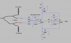
I ran into this problem on a friend's 2.1 system a while ago. This was my solution. It is exactly what AndrewT is telling you about. The 2nd buffer is there to invert the signal back to normal so your sub isn't out of phase with you mains. I disconnected and re-connected this while playing a wide stereo mix to see if I could hear any cross-talk effect and I didn't hear any difference. The 50k pot allows you to do fractional gain all the way down to a very low volume but if it is turned all the way up to 50k:
If left and right channels each have 1V, turning the pot to 50k will output at ~4V so be careful not to overload your subwoofer amp's input. I needed that flexibility but you may not. I used OPA2134 and so far it has been very stable no matter what setting the pot is adjusted to.
I can't speak for the passive line level method but I can tell you that using your amp's speaker level signal and chopping it down to line level will most likely result in a higher noise floor. Some amps are annoyingly noisey. Oh yeah, and only plugging the left channel into the sub amp is no good.
Attachments
Last edited:
I relive this thread and thank you for an answer to this question:
This voltage divider can be applied without problems to an amplifier with output transformers? Valvular, obviously .....
See last post, please ......
http://www.diyaudio.com/forums/subw...gn-eighteen-sound-18lw1400-7.html#post5202581
This voltage divider can be applied without problems to an amplifier with output transformers? Valvular, obviously .....
See last post, please ......
http://www.diyaudio.com/forums/subw...gn-eighteen-sound-18lw1400-7.html#post5202581
I have a similar question. My home stereo receiver amp is a Sony STR-DH190 (100W/channel). It has both an "A" and a "B" speaker outputs, that is it can drive two independent speaker systems (both left and right). The Sony has no sub-woofer out. My speaker is an Infinity RS8A which has in each tower, a built in powered sub-woofer (you plug the Infinity sub-woofer amp into an AC outlet for power). The connection to each sub-woofer is normally a line level sub-woofer out from the amp, which when using the Sony I do not have. The Infinity can use either a line level low pass signal or a full range signal. I have connected the Sony "A" out to the Infinity, minus any connection to the sub-woofer. It works but I'm missing that fuller low end. My question is, is there a way to connect the sub-woofer using the "B" speaker connections? Discussed in this thread is a resistor bridge but I was not clear if this bridge could only be used if a speaker was also attached or if it could be used directly without a speaker attached (obviously I want to make sure I don't hurt the source amplifier by incorrectly loading it)? ....or is there an adapter out there that can load the "B" speaker out correctly and convert the "B" output to the line level appropriate to drive the Infinity sub-woofer? ...any other thoughts or options I missed?
- Status
- This old topic is closed. If you want to reopen this topic, contact a moderator using the "Report Post" button.
- Home
- Source & Line
- Analog Line Level
- Subwoofer circuit: Going from speaker level to line level