Now that my b3's are broken in i'm quite pleased with the sound.
They really do well for such a simple and inexpensive system.
The crossover on the sub is actually much higher, around 150 hz as it was designed to go with the loudpanel system (it's hard to get bass from a picture frame)
The construction on your sub looks great
i'll be interested to hear how that works out because i'll be looking for a sub to go with my other project with some m6 drivers.
Yes, I am also impressed with the B3N. Looking at the specs you'd think the frequency response was a bit ragged but I went with it on the grounds of Zaph's comments and am pleased I did. Sounding really detailed and not harsh at all (once filters are applied).
Sub is just about ready for testing. Worked away preparing that exterior ply baffle last night, driver recess took a while but am quite pleased with it, its the exact smallest cutout my router could do with its "compass" and 16mm bit! Split a bit on one edge but it will join to the MDF side anyhow so no biggie") . heres some pics:
. heres some pics:
What I'd like is some guidence on stuffing. I've not stuffed a BR before and once the side is on most of it will be inaccessible. I presume nothing goes in/near the port as that'll make it a bit aperiodic. I have BAF and lambswool. The tuning seems ok with a good tone if you tap the cone while it sits in the box
Sub is just about ready for testing. Worked away preparing that exterior ply baffle last night, driver recess took a while but am quite pleased with it, its the exact smallest cutout my router could do with its "compass" and 16mm bit! Split a bit on one edge but it will join to the MDF side anyhow so no biggie
. heres some pics:An externally hosted image should be here but it was not working when we last tested it.
An externally hosted image should be here but it was not working when we last tested it.
An externally hosted image should be here but it was not working when we last tested it.
What I'd like is some guidence on stuffing. I've not stuffed a BR before and once the side is on most of it will be inaccessible. I presume nothing goes in/near the port as that'll make it a bit aperiodic. I have BAF and lambswool. The tuning seems ok with a good tone if you tap the cone while it sits in the box
Ok, I applied a single layer to the walls, nothing over the bracing or near the port.
The side is now clamped and being glued on, forever concealing my work .
Will hopefully get some sort of signal test tomorrow. Actually need some screws for the driver, 4mm hex head self tapping are ideal, but I have 5mm only
I did round-over/flare the ends of the ports, with marginal success admittedly. Took a bit of a nip out of one part (bottom right), obviously I needed more to support the router base than was avialable at the bottom edge
The side is now clamped and being glued on, forever concealing my work
. An externally hosted image should be here but it was not working when we last tested it.
Will hopefully get some sort of signal test tomorrow. Actually need some screws for the driver, 4mm hex head self tapping are ideal, but I have 5mm only
I did round-over/flare the ends of the ports, with marginal success admittedly. Took a bit of a nip out of one part (bottom right), obviously I needed more to support the router base than was avialable at the bottom edge
Too many pictures? Surely not
Heres the "finished" sub. Ideally I'd flush trim all the overlaps and roundover the corners then seal it all, but whether I'll actually do any of this I don't know
Haven't done a decent volume test but it does seem to work pretty well. Seems a bit picky about room placement but will have to see how it performs in the actual room concerned. May do a video if I get to test this at a good volume, should actually go quite loud
Onto the satellites I guess. I'm actually thinking about doing a curved back design. They stand quite tall and it would look nice I think. To do it I'm planning on using paper . Many layers with resin based glue in between should actually be very strong when formed in a small curve and supported by ply. We'll see, will keep you updated
Heres the "finished" sub. Ideally I'd flush trim all the overlaps and roundover the corners then seal it all, but whether I'll actually do any of this I don't know
An externally hosted image should be here but it was not working when we last tested it.
An externally hosted image should be here but it was not working when we last tested it.
An externally hosted image should be here but it was not working when we last tested it.
Haven't done a decent volume test but it does seem to work pretty well. Seems a bit picky about room placement but will have to see how it performs in the actual room concerned. May do a video if I get to test this at a good volume, should actually go quite loud
Onto the satellites I guess. I'm actually thinking about doing a curved back design. They stand quite tall and it would look nice I think. To do it I'm planning on using paper
. Many layers with resin based glue in between should actually be very strong when formed in a small curve and supported by ply. We'll see, will keep you updated Some progress with the satellite(s). I have a sort of frame now but can't decide how to make the curved back  . I was originally thinking paper layered up with resin glue but am unsure how to start it off.
Know of any thin, flexible wood type materials I could use? The flexi MDF probably won't take a corner this sharp, need plys about as thin as veneer I expect.
Tiny open baffle anyone
. I was originally thinking paper layered up with resin glue but am unsure how to start it off. Know of any thin, flexible wood type materials I could use? The flexi MDF probably won't take a corner this sharp, need plys about as thin as veneer I expect.
Tiny open baffle anyone
An externally hosted image should be here but it was not working when we last tested it.
if you are still planning on doing the paper over the top you could actually steam strips of balsa which would be able to take some shape. (grain vertical) The paper would have to smooth it out and give it the rigidity you need.
or have you thought about putting in ribs and then laying thin wood, or thin strips over?
or have you thought about putting in ribs and then laying thin wood, or thin strips over?
Unfortunately the satellite is still in that state, having this finished by Saturday is seeming mighty unlikely . A good way to do it is like you say with ribs, mabye lots of long dowell rods drilled into top and bottom, perhaps only requiring a layer of resin (car body filler?) to finish it. Will be difficult now though to get those holes to line up with the panels being fixed with glue.
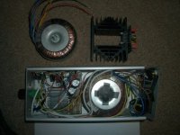
Have got my amplifiers now though. I'm trying to fit them into a rather small case (which looks nice) but may be too much of a challenge to get them in there with power supply and crossovers. Plan is to have main capacitors in the gap between the heatsinks and crossovers will occupy just about any last nook of space, possibly on the roof of the enclosure, above the heatsinks. Would be nice to use SMD but can't really do so . You can see it next to an existing though unfotunately broken 2 channel 2030 chip based amp, the case is the same. I have mounted the amplifier PCBs more compactly as you may be able to see, they are vertical.
. A good way to do it is like you say with ribs, mabye lots of long dowell rods drilled into top and bottom, perhaps only requiring a layer of resin (car body filler?) to finish it. Will be difficult now though to get those holes to line up with the panels being fixed with glue.Have got my amplifiers now though. I'm trying to fit them into a rather small case (which looks nice) but may be too much of a challenge to get them in there with power supply and crossovers. Plan is to have main capacitors in the gap between the heatsinks and crossovers will occupy just about any last nook of space, possibly on the roof of the enclosure, above the heatsinks. Would be nice to use SMD but can't really do so
. You can see it next to an existing though unfotunately broken 2 channel 2030 chip based amp, the case is the same. I have mounted the amplifier PCBs more compactly as you may be able to see, they are vertical.Attachments
Dr.EM said:
I still need to drill more holes
My... there's alot holes there. How did you do that many, must of took some time. Any advice on doing them... tools, tips, etc.
Hi, I used this bench drill:
http://www.machinemart.co.uk/shop/p.../path/drill-presses-magnetic-drilling-systems
with a 25mm flat wood bit (came as part of a set). I drew a grid and literally drilled one after another . I used a pipe fixed to the hoover to extract dust/clumps as the flat type bit removes all the material during drilling as dust. Be wary, the drill motor gets incredibly hot  , I only noticed this later on when I touched it so I reccomend drilling just 6 or so at a time now. I occasionally sprayed the bit with WD40. A hole saw may be more efficient if you get a good one.
http://www.machinemart.co.uk/shop/p.../path/drill-presses-magnetic-drilling-systems
with a 25mm flat wood bit (came as part of a set). I drew a grid and literally drilled one after another
. I used a pipe fixed to the hoover to extract dust/clumps as the flat type bit removes all the material during drilling as dust. Be wary, the drill motor gets incredibly hot , I only noticed this later on when I touched it so I reccomend drilling just 6 or so at a time now. I occasionally sprayed the bit with WD40. A hole saw may be more efficient if you get a good one.Hi
thanks for the tips.
Sorry the reason I asked was very OT, I need to make alot holes venting under the eaves of my home. Thinking of 2 1/8" dia holes into 1.5" thickness of dry pine wood. Planning to do about 30 holes or so. My baseline plan is to buy a good hole saw as well pre-drilling 2-3 holes at the circumference to allow saw dust to escape. Just thought you might have the easy answer there on your project.
Dr.EM said:Ok, it sounds like the specs on the B3Ns may not be that accurate so i'll probably have to do some experimenting/measuring anyhow. Assuming that latest crossover is a good starting point how would I actually go about making it? Where can I find the schematic of this custom filter with equations to calculate Q?
A quick question on the sub too since I'd like to start cutting wood today for it. Can the port be done as per image 1 (where the bottom part of the enclosure forms one side of the slot port) or must it be done as per image 2 with two free edges?
Dr em,
excellent wood work . A suggestion on the internal braces, the holes should be of varying sizes either on the same baffle or from baffle to baffle.
How do you find the Hi vi sub ? in the past their driver consistency was a problem for me .
A.Wayne
Hi A.Wayne, I did sort of know about varying the sizes of the holes but assumed it was to avoid a sort of resonator effect where all the holes have the same resonant frequency the effect would be worse. If that is it, the resonant frequency would be so high as not to matter in my application, but I may be completely wrong and it may be something structural instead.
I have found the sub very good. I posted a video of the nice clean excursion it has, no motor noise at all really. The tuning of the cabinet was successful based on the manufacturers TS specs so they must be quite accurate too. Unfortunately I only have one driver so can't compare any to check consistency. I have two D10G woofers but these will go into a sealed box where TS won't be so critical.
I used a hole saw for the two large holes on that satellite frame. I did use hardboard underneath. I did with the flat wood bit too where it was essential or it would plunge into the bench drills metal table!
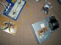
Bad news is theres no chance of finishing this today so I'll need to use headphones for a while . I have made some progress with the amplifier unit, though the transformer I've decided will be seperate. The crossovers are nearly done now so I just have to make the power supply board and mount everything in the case. Then I will need my satellites o ) and said transformer box.
I have found the sub very good. I posted a video of the nice clean excursion it has, no motor noise at all really. The tuning of the cabinet was successful based on the manufacturers TS specs so they must be quite accurate too. Unfortunately I only have one driver so can't compare any to check consistency. I have two D10G woofers but these will go into a sealed box where TS won't be so critical.
I used a hole saw for the two large holes on that satellite frame. I did use hardboard underneath. I did with the flat wood bit too where it was essential or it would plunge into the bench drills metal table!
Bad news is theres no chance of finishing this today so I'll need to use headphones for a while
. I have made some progress with the amplifier unit, though the transformer I've decided will be seperate. The crossovers are nearly done now so I just have to make the power supply board and mount everything in the case. Then I will need my satellites o ) and said transformer box.Attachments
- Status
- This old topic is closed. If you want to reopen this topic, contact a moderator using the "Report Post" button.
- Home
- Loudspeakers
- Multi-Way
- Sub sat system design