Hi,
I'd like to build a mini guitar amp for my 7 yr old son.
He's got his first 3 strings cigar box guitar that he built with me, but we found that the sound is not loud enough to annoy his mother")
I searched and found a few schematics like :
from http://jjs.at/
or
I have a few russian subminiature tubes 6n16 & 6n17 that I used to mod an Hammond T500 organ, and I bought some 6P30B.
As it looks like that the 6p30b is a drop in replacement for 5902.
Anyway, I can understand triodes, but for pentodes I feel lost.
Could someone point me to a good ressource so I could understand how those PP amps work and how they are designed so I could mod them myself ?
I searched google, but I might not have the right english words (not my mother tongue).
Feel free to move the post to another topic, I did not know where to post.
Thanks a lot.
I'd like to build a mini guitar amp for my 7 yr old son.
He's got his first 3 strings cigar box guitar that he built with me, but we found that the sound is not loud enough to annoy his mother
I searched and found a few schematics like :
from http://jjs.at/
or
An externally hosted image should be here but it was not working when we last tested it.
I have a few russian subminiature tubes 6n16 & 6n17 that I used to mod an Hammond T500 organ, and I bought some 6P30B.
As it looks like that the 6p30b is a drop in replacement for 5902.
Anyway, I can understand triodes, but for pentodes I feel lost.
Could someone point me to a good ressource so I could understand how those PP amps work and how they are designed so I could mod them myself ?
I searched google, but I might not have the right english words (not my mother tongue).
Feel free to move the post to another topic, I did not know where to post.
Thanks a lot.
Merlin Blencowe (aka the Valve Wizard) has a helpful page on small-signal pentodes on his website: The Valve Wizard -Small Signal Pentode
This will get you through pentode basics, including understanding what to do with that extra grid lead, figuring out what load impedance you need from your output transformer, and so on.
For "classic" power pentodes, the main difference from small-signal pentodes seems to be that the screen voltage is usually quite large, often fairly close to the anode voltage.
Once you draw the maximum anode dissipation curve onto your 5902 data, you can probably figure out a screen voltage that will work for you. Worst case, start with a too-big screen grid resistor, set your (grid 1) bias voltage to something reasonable (cathode current will now be too small), monitor cathode current, and gradually decrease the screen grid resistor - raising the screen grid voltage - until you end up with the output cathode current you want.
Now you know what screen grid voltage you need.
The big screen grid resistor technique is enough to tell you this, but you probably can't leave it in place once you start driving your amp hard - screen grid voltage will drop during overdrive.
So you may then have to figure out how to tweak your power supply to produce this desired screen grid voltage with a reasonably low impedance, so there isn't too much sag during overdrive.
I've managed to get a few oddball pentodes working using this sort of approach. Hopefully you will have equal success.
-Gnobuddy
Thanks Gnobuddy,
I already read the Valve Wizard before asking and as the author says, it's not as complete as his book, that I might buy
I am currently reading tube courses and I will make a test bench as you suggest and as it's suggested in the papers.
When I'll be done, I'll put a few lines in the forum with the schematics
On behalf of the kid, I suggest something simpler, so it gets done before he is 8.
On behalf of his mother, and your neighbors, I suggest something smaller. 300V amps rock the whole block. A part-Watt amp is really plenty for in-home no-drummer use. (Tell me the kid's friend is a drummer.)
Hah! This plan is older than your kid!
This plan is an inside joke. Someone said the 6AU6 is not a power amp. "Sure it is!" I say, "just a very small power amp!" Another person wondered if there were anything smaller than a 6V6 Champ amp. I pulled up the first Champ (used 6AU6 preamp) and cobbled it. The OT has to be higher Z (Fender Reverb is suitable) and the supply voltage has to be lower.
Builders report it plays OK, louder than they expected, but indeed in the same speaker it is no Champ Amp.
"6AU6" can be almost any pentode rated for "IF amplifier" work. (But NOS 6AU6 is as cheap as anything.)
See the pot on V2, feeding the "extra grid"? This is an aspect of pentode operation. For a first-build, I suggest you omit the pot and wire screen (pin 6 on 6AU6) right to the B+. Full Voltage on Screen. Maximum output.
When mother complains, add the pot. As you turn it down, maximum power output drops from the whopping 0.3 Watts to 0.1W, 0.03W, and finally fizzles out when the tube is too starved to pull any load at all. (Don't say Power Scaling, that is someone else's trademark.)
Attachments
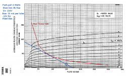
I did a little fiddling around with Catslab's original concept (push-pull 5902 or equivalent Russian valves.)
My quick-n-dirty load line attached. Easily obtained 8k Raa push-pull transformer, 150V B+, 100 volts on the screen grids, roughly -16 volts for fixed-bias operation, 15 mA idle current per valve as a starting point. Estimated 4 watts RMS audio output power. (Enough to be very loud in a home!)
As per PRR's suggestion, a 120V:120V isolation transformer feeding a (silicon) diode bridge would probably be a good way to get the 150V DC B+ voltage. Some experimenting needed to find the right resistors to get 100V for the screen grids, or one could even use a 100V, 5W zener diode and series resistor.
-Gnobuddy
Attachments
Thanks guys
Sir PPR: yes I'll try to have it done before he's 8
This would not be my first tube amp ( 300B ), nor my second (EL34), but I always took schematics from other in magazines or books.
It was hifi so supposed to be low on distortion not quite like guitar amps, another world for me.
I know a single watt can be loud, depending on the speaker. I'll throw a celestion eight 15 at it, should be ok.
I'll have a closer look at your schematic
That said, the aim was to come back to tubes, as it's been well over a decade.
I still work in electronics but more in data acquisition and processing. Far away from audio field.
Gnobuddy: yes, that's exactly what I was trying to do.
I wasn't remembering (may be I never knew) how to trace for pentodes in PP but I read a few articles on tube power amps originally released in a french magazine, and I think I understood !
I have a handfull of those 6p30b-r pentodes on the desk, and I could go as per the datasheet 120V for G2.
I asked myself, what if I'd throw 230V like on the schematics I posted ?
Found the answer a bit later:get a tube tracer and trace !
I do not have one, might take ages to build one and I don't know anyone who could trace for me.
So I'll first build a power supply to experiment the amp part on the bench. Then I'll grab a preamp schematic and I'll adapt it to the triodes I have.
I found a few sovtek 12ax7 and rifa HV paper caps that I bought 20 years ago as per the receipt and they miraculously followed me when I moved oversea.
Sir PPR: yes I'll try to have it done before he's 8
This would not be my first tube amp ( 300B ), nor my second (EL34), but I always took schematics from other in magazines or books.
It was hifi so supposed to be low on distortion not quite like guitar amps, another world for me.
I know a single watt can be loud, depending on the speaker. I'll throw a celestion eight 15 at it, should be ok.
I'll have a closer look at your schematic
That said, the aim was to come back to tubes, as it's been well over a decade.
I still work in electronics but more in data acquisition and processing. Far away from audio field.
Gnobuddy: yes, that's exactly what I was trying to do.
I wasn't remembering (may be I never knew) how to trace for pentodes in PP but I read a few articles on tube power amps originally released in a french magazine, and I think I understood !
I have a handfull of those 6p30b-r pentodes on the desk, and I could go as per the datasheet 120V for G2.
I asked myself, what if I'd throw 230V like on the schematics I posted ?
Found the answer a bit later:get a tube tracer and trace !
I do not have one, might take ages to build one and I don't know anyone who could trace for me.
So I'll first build a power supply to experiment the amp part on the bench. Then I'll grab a preamp schematic and I'll adapt it to the triodes I have.
I found a few sovtek 12ax7 and rifa HV paper caps that I bought 20 years ago as per the receipt
and they miraculously followed me when I moved oversea.There is an archaic, complex, elegant, and quite unnecessary way of combining the curves from two valves in push-pull into one giant set of compound curves; I've seen it in a few books from the valve era.I wasn't remembering (maybe I never knew) how to trace for pentodes in PP
That is probably the "right" way to do push-pull, but I've never seen the necessity for it, especially since pentodes and transformers both have fairly large tolerances, and even more especially since we're talking about guitar amps, and not trying to get things as linear as they could possibly be.
So I just look at one set of curves, but bias it for class AB, rather than class A, as you'd do for a single-ended amp. And I allow for the fact that the anode-to-anode load impedance for push-pull is four times the impedance seen by one transistor.
Technically there should be a kink in the load-line at the point where the operating point moves from class A to class B, but once again, we're talking about guitar amps here...
So the rough starting point I showed on that image should be enough to get your project going, if you choose.
The most probable answer is that you'd get destroyed output pentodes, particularly since these are subminiature tubes with electrodes crammed into a tiny, tiny envelope. But there's only one way to be 100% sure!I asked myself, what if I'd throw 230V like on the schematics I posted ?
Sounds like a plan! Good luck!So I'll first build a power supply to experiment the amp part on the bench. Then I'll grab a preamp schematic and I'll adapt it to the triodes I have.
-Gnobuddy
Technically there should be a kink in the load-line at the point where the operating point moves from class A to class B, but once again, we're talking about guitar amps here...
I tried the method as per the book on a kt88 curve, there is a kink, but it's said to be a smooth transition in real life.
For a guitar, yes, I'd be tempted to say: who cares while it makes noise
The most probable answer is that you'd get destroyed output pentodes, particularly since these are subminiature tubes with electrodes crammed into a tiny, tiny envelope. But there's only one way to be 100% sure!
Max anode is 250V, cutoff at 350V and I have military versions.
There's only one way to know if what they says is true.
Over the time I specialized in destructive tests in the lab, at some point.
When I announce that I'm about to test a new thing, my technician steps back, puts the safety googles on and grabs a fire extinguisher. Dunno why
That reminds me of the late 1990's, when some of my (then) colleagues were trying to design and prototype fairly high-powered switching power supplies.When I announce that I'm about to test a new thing, my technician steps back, puts the safety googles on and grabs a fire extinguisher. Dunno why
Every now and then we would hear a loud bang, followed by a couple of technicians and engineers walking around trying to shake the ringing out of their ears, followed by the acrid smell of burnt electronics.
With large amounts of stored energy, and nothing to limit current through the switching inductor except perfectly timed switching, those switching supplies were hard things to get right!
Back to the submini power tubes, mebbe send George (Tubelab on diyAudio) a PM and ask if he has any input. One of his specialities is taking tubes far beyond their ratings whenever possible. He knows what he's doing, so he often extracts ungodly amounts of performance from otherwise mediocre valves. I don't know if he's ever dealt with subminiature tubes, but it's probably worth a PM.
-Gnobuddy
Happy New year !
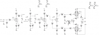
I drawn a schematic of the amp
I just thrown values for the components. I did not calculated any for now. This is just a pre alpha version.
The power will be around 120V for the screen, and I do not know what will be the B+. It might be 120V as well...
I received a utracer just before the holidays and I began to trace some submini tubes.
I drawn a schematic of the amp
An externally hosted image should be here but it was not working when we last tested it.
I just thrown values for the components. I did not calculated any for now. This is just a pre alpha version.
The power will be around 120V for the screen, and I do not know what will be the B+. It might be 120V as well...
I received a utracer just before the holidays and I began to trace some submini tubes.
Catslab, I can't see your schematic. It looks like a link to a Google Drive account, perhaps one not set for public access.
When typing up a post to this forum, you can just use the "Go Advanced" button at the bottom of the text entry window, and attach a local file from your computer. That avoids many of these remote server related issues.
-Gnobuddy
When typing up a post to this forum, you can just use the "Go Advanced" button at the bottom of the text entry window, and attach a local file from your computer. That avoids many of these remote server related issues.
-Gnobuddy
I couldn't see it, it wouldn't load for me. It won't be the first time the software that runs this forum has had a problem with remotely hosted image files...Yes it's on google but it's public....
Thanks! Works for me this time!anyway I attached the file.
Let me know !

There's no grid-leak shown for V3B in the schematic - an oversight? That grid needs to be tied to zero volts DC.
I know nothing about any of these tubes, so I look forward to hearing how it all works out as you build it.
Any interest in reviving the "Hundred Buck Amp Challenge" sticky thread with your new amp design? I'd love to see that thread come back to life. (And a $100 budget is no longer a constraint, the challenge ended, and the thread morphed over the years, and lately it's been more about original, low power, somewhat low-cost designs and builds.)
-Gnobuddy
You might like to check out some of the small amp designs on http://www.harmonicappliances.com such as the Powerman and the Pentotron. The Firefly and Trinity Amps' Superfly variant are also great low power amps, using a single PP 12AU7 power stage.
Sent from my LG G2 with CM13 using Tapatalk
Sent from my LG G2 with CM13 using Tapatalk
Gnobuddy: no leak resistor, in fact there's the volume pot there.
I put pads because I will not mount the pots on the board.
That said, I will test it and see if it's worse posting it in the under 100$
AquaTarkus: thanks for the links. I already saw the Firefly but can't remember the Trinity one.
I put pads because I will not mount the pots on the board.
That said, I will test it and see if it's worse posting it in the under 100$
AquaTarkus: thanks for the links. I already saw the Firefly but can't remember the Trinity one.
Thanks, AquaTarkus! I've seen some of those before (Firefly, Pentotron), but not all of them. I'll look them up.You might like to check out some of the small amp designs on Harmonic Appliances – A man and his musical projects… such as the Powerman and the Pentotron. The Firefly and Trinity Amps' Superfly variant are also great low power amps, using a single PP 12AU7 power stage.
-Gnobuddy
Okay, I see!Gnobuddy: no leak resistor, in fact there's the volume pot there.
I put pads because I will not mount the pots on the board.
For myself, I don't trust potentiometers to always maintain contact. As pots age, the wiper usually goes open-circuit at some positions along its range of movement. So I don't rely on them to maintain DC operating conditions.
My two cents: adding a grid leak resistor (in parallel with the lower half of the pot) would eliminate any concern. If the pot ages and its wiper goes open-circuit, the triode will still be properly biased.
Please do! And if you don't think it's worth posting as-is, there were a lot of smart, experienced people with tube knowhow on that thread, so it's quite possible some of them might help you to improve the amp.That said, I will test it and see if it's worse posting it in the under 100$
-Gnobuddy
If it's an audio/log pot, I would prefer to place the grid reference resistor across the whole pot, so that the pot maintains its correct law. Alternatively, strapping the resistor to the wiper of a linear pot will give you a logarithmic end result. I think plastic pots should be more reliable than carbon in the long run. So that may be another option.
Harmonic Alliances' Powerman also users subminiature tubes, although they're triodes. The power stage is self-split, so it doesn't need a separate PI, but will only work in Class A. BTW it had a volume put being used as a grid reference I haven't heard this amp in person, but I have heard Zvex's Nanohead, which also uses submini tubes, and it has a wonderfully crisp tone.
Sent from my LG G2 with CM13 using Tapatalk
Harmonic Alliances' Powerman also users subminiature tubes, although they're triodes. The power stage is self-split, so it doesn't need a separate PI, but will only work in Class A. BTW it had a volume put being used as a grid reference
I haven't heard this amp in person, but I have heard Zvex's Nanohead, which also uses submini tubes, and it has a wonderfully crisp tone. Sent from my LG G2 with CM13 using Tapatalk
Last edited:
- Status
- This old topic is closed. If you want to reopen this topic, contact a moderator using the "Report Post" button.
- Home
- Live Sound
- Instruments and Amps
- Sub miniature pentode push pull design help