Hi everyone,
It’s time for me to share yet another of my designs. I have earlier posted the SAL451 loudspeaker http://www.diyaudio.com/forums/multi-way/160225-sal451-small-2-way-loudspeaker.html and it’s a wonderful sounding small speaker.
This time I’m going up a notch in box size and driver unit size, but it’s still a relatively small 2-way stand mount loudspeaker.
Be aware! There will be a lot of pictures and diagrams presented here. Even though there are a lot of skilled designers out there I’m always missing more details from measurements and simulations etc. in their designs. It’s hard to evaluate a design showing only one simulated on-axis frequency measurement with a smoothed frequency plot in a 100db/scale and perhaps only a reverse polarity simulation to show phase response etc.
Even though the language barrier, I will try to be more informative in my design and I think a picture can tell you more than a thousand words.
Measurements:
I can not overstate the importance of accurate measurements. In my opinion, without it, it’s no use to continue with a loudspeaker design. It would all be guesswork and the result will be accordingly. I will here shortly describe how my frequency measurements are set up.
1. All measurements are done with the drivers mounted in the actual box used in the design.
2. The loudspeaker box is elevated on a stand mounted on a turntable so that the tweeter centre is halfway between the floor and the ceiling.
3. The microphone is setup at a 1m distance from the tweeter centre.
4. Individual measurements are done for the tweeter and woofer from this position. A measurement with both tweeter and woofer connected simultaneously are done as a reference curve to import in LspCAD to get the correct acoustical offset and phase between the drivers.
5. All above measurements are repeated without moving the microphone for on-axis, 15, 22.5, 30, 45 degree off-axis angle. These measurements are done for both loudspeaker boxes.
6. The measurements are supplemented with near field measurements at 0 and 25cm distance from the woofer cone.
The measurements are valid down to approximately 270Hz in this setup. Are there other ways to measure? Of course, but this method is easy to setup and is fast and accurate. I don’t have the space to measure semi infinite baffle measurements etc.
I use the following tools for my design work:
In order to get accurate measurements you need some reliable tools and you need a calibrated microphone and a calibrated measurement rig. Previously I used a Clio measurement system, but nowadays I use the great free tool “HolmImpulse” for frequency measurements. I highly recommend this software. It’s accurate and very easy to use; give it a try for yourself. For box and cross-over simulation I use LspCAD. It’s not for free, but is a great tool. I have earlier used Calsod and Sound Easy, but in my opinion LspCAD is far superior software to use.
Here’s a list of tools I use:
• Dayton WT3 tester for impedance and T/S parameter measurements. (Dayton Audio - WT3 Woofer Tester)
• HolmImpulse with M-Audio Audiophile 24/96 soundcard for frequency measurements. (HOLM Acoustics)
• LspCAD 6 Pro/5.25 for crossover design and simulation. (Untitled)
• EMM-8cal and MP-1r calibrated mic and pre-amp. (www.ibf-akustik.de)
Driver units:
Yet again I use drivers from my favourite speaker manufacturer, SEAS. I think SEAS drivers have a great price/performance value and great build consistency and quality to back it up. I’m aware that SEAS prices are a bit higher in the USA than here in Europe, but I still think SEAS drivers are nice drivers for its price range.
The drivers are:
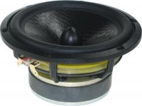
SEAS U16RCY/P (H1520) build week/year 39/09 Picture1
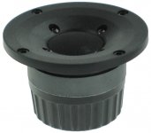
SEAS 27TBCD/GB-DXT (H1499) build week/year 7/08 Picture2
Woofer:
I chose a woofer driver that I haven’t seen in a DYI design before. SEAS released a design “Idunn” with its bigger brother U18RNX/P (H1571) and the same Tweeter. Zaph Audio has done some measurements of this U16RCY/P driver.
Here is how SEAS describes the driver:
“U16RCY/P is a 5” High Fidelity woofer with an injection moulded metal chassis, intended for bass reflex and transmission line designs.
New Curve cone, a woven polypropylene with excellent internal damping together with perfectly matched moving parts gives a smooth, extended frequency response.
A unique radial reinforced low loss rubber surround reduces radial resonances and prevents surround break up at large excursions.
Bullet shaped phase plug reduces compression due to temperature variations in the voice coil, avoids resonance problems which would occur in the volume between the dust cap and the pole piece and increases the long term power handling capacity.
Extremely stiff and stable injection moulded metal basket, keeps the critical components in perfect alignment. Large windows in the basket both above and below the spider reduce sound reflection, airflow noise and cavity resonance to a minimum.”
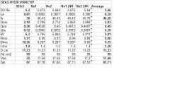
This time SEAS has published specification sheets that are far off the actual measurements. See Picture3. The voice-coil doesn’t seem to be same between the official specification and the real driver unit. The consistency between the measured drivers is great.
The official specification shows a frequency peak at 5000Hz that doesn’t show up so pronounced in my measurements. There is however irregularities between 800-1200Hz most likely due to cone surround resonances and diffraction issues. These suck-outs and peaks are also clearly shown in the impedance plots. In my design the cut-out for the woofer is chamfered, otherwise it would bee even more noticeable in the frequency response.
It’s hard to tell if these irregularities can be heard. Zaphs distortion measurements show a 2nd order peak at 1200Hz. 2nd order distortion isn’t as bad as odd order distortion which in this case is under control.
Since the cone breakup is so gentle, it’s very easy to get a smooth frequency roll-off with this woofer without the need of any notch filter. This is more like a 5.5” driver, but fitted in a 5” driver frame.
Tweeter:
I have used this tweeter successfully in an active design before and it has gained some reputation in the DIY community thanks to its performance and the DXT technology. Both Zaph and Mark K have done extensive tests of this driver.
Here is how SEAS describes the driver:
“27TBCD/GB-DXT is a High Definition aluminium/magnesium alloy dome tweeter with a DXT lens. An optimally shaped dome and a wide SONOMEX surround both manufactured by SEAS, ensure excellent performance and consistency.
The compensation magnet increases the sensitivity and reduces the magnetic stray field and allows use in close proximity to CRT screens.
A fine mesh grid protects the diaphragm. Stiff and stable rear chamber with optimal acoustic damping allows the tweeter to be used with moderately low crossover frequencies.
This revolutionary DXT tweeter addresses the major issues regarding directivity control in traditional loudspeaker designs. DXT solves several well-know issues regarding; directivity control, off-axis response, integration with midrange units and baffle diffractions.”
My measurements don’t show a significant change from the official specification sheets. It’s a very sensitive driver; around 95-96db and thanks to its DXT lens it has a remarkable off-axis response.
Next, design goals……….
It’s time for me to share yet another of my designs. I have earlier posted the SAL451 loudspeaker http://www.diyaudio.com/forums/multi-way/160225-sal451-small-2-way-loudspeaker.html and it’s a wonderful sounding small speaker.
This time I’m going up a notch in box size and driver unit size, but it’s still a relatively small 2-way stand mount loudspeaker.
Be aware! There will be a lot of pictures and diagrams presented here. Even though there are a lot of skilled designers out there I’m always missing more details from measurements and simulations etc. in their designs. It’s hard to evaluate a design showing only one simulated on-axis frequency measurement with a smoothed frequency plot in a 100db/scale and perhaps only a reverse polarity simulation to show phase response etc.
Even though the language barrier, I will try to be more informative in my design and I think a picture can tell you more than a thousand words.
Measurements:
I can not overstate the importance of accurate measurements. In my opinion, without it, it’s no use to continue with a loudspeaker design. It would all be guesswork and the result will be accordingly. I will here shortly describe how my frequency measurements are set up.
1. All measurements are done with the drivers mounted in the actual box used in the design.
2. The loudspeaker box is elevated on a stand mounted on a turntable so that the tweeter centre is halfway between the floor and the ceiling.
3. The microphone is setup at a 1m distance from the tweeter centre.
4. Individual measurements are done for the tweeter and woofer from this position. A measurement with both tweeter and woofer connected simultaneously are done as a reference curve to import in LspCAD to get the correct acoustical offset and phase between the drivers.
5. All above measurements are repeated without moving the microphone for on-axis, 15, 22.5, 30, 45 degree off-axis angle. These measurements are done for both loudspeaker boxes.
6. The measurements are supplemented with near field measurements at 0 and 25cm distance from the woofer cone.
The measurements are valid down to approximately 270Hz in this setup. Are there other ways to measure? Of course, but this method is easy to setup and is fast and accurate. I don’t have the space to measure semi infinite baffle measurements etc.
I use the following tools for my design work:
In order to get accurate measurements you need some reliable tools and you need a calibrated microphone and a calibrated measurement rig. Previously I used a Clio measurement system, but nowadays I use the great free tool “HolmImpulse” for frequency measurements. I highly recommend this software. It’s accurate and very easy to use; give it a try for yourself. For box and cross-over simulation I use LspCAD. It’s not for free, but is a great tool. I have earlier used Calsod and Sound Easy, but in my opinion LspCAD is far superior software to use.
Here’s a list of tools I use:
• Dayton WT3 tester for impedance and T/S parameter measurements. (Dayton Audio - WT3 Woofer Tester)
• HolmImpulse with M-Audio Audiophile 24/96 soundcard for frequency measurements. (HOLM Acoustics)
• LspCAD 6 Pro/5.25 for crossover design and simulation. (Untitled)
• EMM-8cal and MP-1r calibrated mic and pre-amp. (www.ibf-akustik.de)
Driver units:
Yet again I use drivers from my favourite speaker manufacturer, SEAS. I think SEAS drivers have a great price/performance value and great build consistency and quality to back it up. I’m aware that SEAS prices are a bit higher in the USA than here in Europe, but I still think SEAS drivers are nice drivers for its price range.
The drivers are:
SEAS U16RCY/P (H1520) build week/year 39/09 Picture1
SEAS 27TBCD/GB-DXT (H1499) build week/year 7/08 Picture2
Woofer:
I chose a woofer driver that I haven’t seen in a DYI design before. SEAS released a design “Idunn” with its bigger brother U18RNX/P (H1571) and the same Tweeter. Zaph Audio has done some measurements of this U16RCY/P driver.
Here is how SEAS describes the driver:
“U16RCY/P is a 5” High Fidelity woofer with an injection moulded metal chassis, intended for bass reflex and transmission line designs.
New Curve cone, a woven polypropylene with excellent internal damping together with perfectly matched moving parts gives a smooth, extended frequency response.
A unique radial reinforced low loss rubber surround reduces radial resonances and prevents surround break up at large excursions.
Bullet shaped phase plug reduces compression due to temperature variations in the voice coil, avoids resonance problems which would occur in the volume between the dust cap and the pole piece and increases the long term power handling capacity.
Extremely stiff and stable injection moulded metal basket, keeps the critical components in perfect alignment. Large windows in the basket both above and below the spider reduce sound reflection, airflow noise and cavity resonance to a minimum.”
This time SEAS has published specification sheets that are far off the actual measurements. See Picture3. The voice-coil doesn’t seem to be same between the official specification and the real driver unit. The consistency between the measured drivers is great.
The official specification shows a frequency peak at 5000Hz that doesn’t show up so pronounced in my measurements. There is however irregularities between 800-1200Hz most likely due to cone surround resonances and diffraction issues. These suck-outs and peaks are also clearly shown in the impedance plots. In my design the cut-out for the woofer is chamfered, otherwise it would bee even more noticeable in the frequency response.
It’s hard to tell if these irregularities can be heard. Zaphs distortion measurements show a 2nd order peak at 1200Hz. 2nd order distortion isn’t as bad as odd order distortion which in this case is under control.
Since the cone breakup is so gentle, it’s very easy to get a smooth frequency roll-off with this woofer without the need of any notch filter. This is more like a 5.5” driver, but fitted in a 5” driver frame.
Tweeter:
I have used this tweeter successfully in an active design before and it has gained some reputation in the DIY community thanks to its performance and the DXT technology. Both Zaph and Mark K have done extensive tests of this driver.
Here is how SEAS describes the driver:
“27TBCD/GB-DXT is a High Definition aluminium/magnesium alloy dome tweeter with a DXT lens. An optimally shaped dome and a wide SONOMEX surround both manufactured by SEAS, ensure excellent performance and consistency.
The compensation magnet increases the sensitivity and reduces the magnetic stray field and allows use in close proximity to CRT screens.
A fine mesh grid protects the diaphragm. Stiff and stable rear chamber with optimal acoustic damping allows the tweeter to be used with moderately low crossover frequencies.
This revolutionary DXT tweeter addresses the major issues regarding directivity control in traditional loudspeaker designs. DXT solves several well-know issues regarding; directivity control, off-axis response, integration with midrange units and baffle diffractions.”
My measurements don’t show a significant change from the official specification sheets. It’s a very sensitive driver; around 95-96db and thanks to its DXT lens it has a remarkable off-axis response.
Next, design goals……….
Attachments
Design goals:
When I initially started to plan the new design I only had one absolute demand, the design should fit the Parts Express 14liter curved cabinet. Although I like woodworking, nowadays I don’t have the time or patience to build new boxes for each new design and the Parts Express boxes are really nicely built.
By choosing a mid-sized stand-mount cabinet the most logical is to build a 2-way speaker, but what drivers should I use in this relative small cabinet? The box is a bit to big for most 5” drivers and to small for most 6.5-7” drivers. I could of course use a 5” driver and fill up the box with something solid to reduce the volume. At the same time I wanted to have a design that could play bass without the need for a subwoofer. The choice fell to use a 5.5” driver. First I looked at the ScanSpeak drivers from the 15W series. These drivers have a solid reputation and sound great. I didn’t choose them, primarily because they are very commonly used in different DIY designs and they are in my opinion a bit to low in sensitivity.
I finally decided to use a 5.5” driver from SEAS. There are three different flavours of SEAS drivers in this size, the L16, W16 and the U16. I wanted to use the woofer a bit up in frequency, around 2500Hz and that unfortunately rules out the W16 and even more so the L16 due to nasty cone break-up. They both require low cross-over frequencies around 1400-2000Hz. I might however use the Excel W16 driver in a different design in the future.
Ok, the U16 is the driver I selected. It has a very smooth frequency roll-off and should be easy to mate with a tweeter around 2500Hz.
What about the tweeter? I looked around for a new tweeter to buy, but decided to use a tweeter I had in stock. I have several nice tweeters to choose from like the 27TDFC, 27TBFC/G and a couple of different ribbon tweeters from Fountek. Finally I decided to use the 27TBCD/GB-DXT driver with its unique DXT-lens technology.
This driver with its unique frequency response isn’t the easiest beast to tame and I like the challenge to make it work in the design without overcomplicating the cross-over design. The goal is to build as a simple cross-over as possible and to use standard component values with as few parts as possible.
Summing up the design goals:
• Parts Express 14liter box “302-721s”.
• Smooth system power response and off-axis frequency response.
• Cross-over frequency around 2500 Hz.
• Cross-over slopes, 4th order Linkwitz Riley, acoustical.
• Bass extension down to low 40ies.
• Simple crossover with standard component values.
• Adjustable tweeter level.
Next, Box simulation and design…….
Box simulation and design:
There is nothing special here since I have already chosen the 14liter enclosure from Parts Express. 14liter is just about what it takes for this driver when a coil resistance of 0.3-0.5 is included in the equation. Don’t stare blindly at what some simulation software might suggest for box volume. These suggestions are mostly theoretical text-book table lookups and have little to do with real world scenarios. In my experience a closed enclosure volume with a total Q of around 0.55-0.65 often fits to use for bass-reflex enclosures.
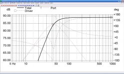
Picture1: show how a simulated 14liter box with a 44Hz port tuning and an added resistance of 0.5 Ohm looks like.
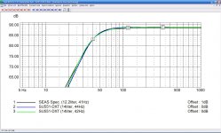
Picture2: show how a simulated 14liter box with different port tunings looks like compared to a text-book simulation with driver data from SEAS original specification sheet. All three examples have an added resistance of 0.5 Ohm.
I suggest using a port tuning between 42-44Hz or even a bit lower depending on room interaction and loudspeaker room placement. It’s up to the builder to decide which port tuning to use based on their personal preferences. I would say its ok to adjust +/- 10% to box volume, port tuning and box filling. I use about 20% sheep wool box filling.
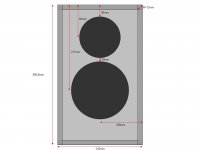
Picture3: show the loudspeaker baffle layout. Don’t forget to use the same baffle round-over if you are building the loudspeaker enclosure yourself. It’s absolutely critical that the driver unit baffle placements are kept as the described picture, otherwise the frequency response and the cross-over won’t be correct.
Next, frequency measurements…..
There is nothing special here since I have already chosen the 14liter enclosure from Parts Express. 14liter is just about what it takes for this driver when a coil resistance of 0.3-0.5 is included in the equation. Don’t stare blindly at what some simulation software might suggest for box volume. These suggestions are mostly theoretical text-book table lookups and have little to do with real world scenarios. In my experience a closed enclosure volume with a total Q of around 0.55-0.65 often fits to use for bass-reflex enclosures.
Picture1: show how a simulated 14liter box with a 44Hz port tuning and an added resistance of 0.5 Ohm looks like.
Picture2: show how a simulated 14liter box with different port tunings looks like compared to a text-book simulation with driver data from SEAS original specification sheet. All three examples have an added resistance of 0.5 Ohm.
I suggest using a port tuning between 42-44Hz or even a bit lower depending on room interaction and loudspeaker room placement. It’s up to the builder to decide which port tuning to use based on their personal preferences. I would say its ok to adjust +/- 10% to box volume, port tuning and box filling. I use about 20% sheep wool box filling.
Picture3: show the loudspeaker baffle layout. Don’t forget to use the same baffle round-over if you are building the loudspeaker enclosure yourself. It’s absolutely critical that the driver unit baffle placements are kept as the described picture, otherwise the frequency response and the cross-over won’t be correct.
Next, frequency measurements…..
Attachments
Thank you for sharing and comprehensively documenting your design. I just read your prior speaker build and am amazed at your logical and detailed approach to speaker design. I especially like that you compared your work to another respected diy builder, Zaph. Please keep us posted on your progress.
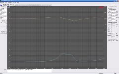
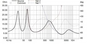
Impedance measurements:
The pictures show the two driver unit samples, named 1L and 2R. The measurements are made with the drivers mounted on the baffle.
Woofer:
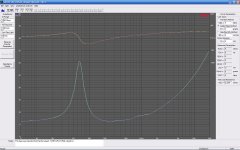
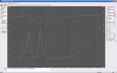
The consistency between the two woofer driver samples is great. There are some wrinkles in the impedance plot at 850Hz and 1200Hz. These wrinkles also show up at the frequency plots and are most likely caused by surround resonances and cone diffractions.
Tweeter:
The consistency between the two tweeter driver samples is also good. The 2R sample has slightly higher impedance than the 1L around the resonance frequency. According to SEAS specification the resonance frequency is at 900Hz. It’s hard to tell due to the double impedance bump at lower frequencies, but my guess is around 550-600Hz a bit lower than the official specification.
Picture1: U16RCY/P closed box, blue = 1L, green = 2R
Picture2: U16RCY/P bass-reflex box, port tuning = 44Hz, blue = 1L, green = 2R
Picture3: 27TBCD/GB-DXT, blue = 1L, green = 2R
Next, frequency measurements…..
The pictures show the two driver unit samples, named 1L and 2R. The measurements are made with the drivers mounted on the baffle.
Woofer:
The consistency between the two woofer driver samples is great. There are some wrinkles in the impedance plot at 850Hz and 1200Hz. These wrinkles also show up at the frequency plots and are most likely caused by surround resonances and cone diffractions.
Tweeter:
The consistency between the two tweeter driver samples is also good. The 2R sample has slightly higher impedance than the 1L around the resonance frequency. According to SEAS specification the resonance frequency is at 900Hz. It’s hard to tell due to the double impedance bump at lower frequencies, but my guess is around 550-600Hz a bit lower than the official specification.
Picture1: U16RCY/P closed box, blue = 1L, green = 2R
Picture2: U16RCY/P bass-reflex box, port tuning = 44Hz, blue = 1L, green = 2R
Picture3: 27TBCD/GB-DXT, blue = 1L, green = 2R
Next, frequency measurements…..
Attachments
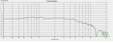
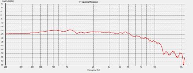
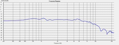
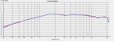
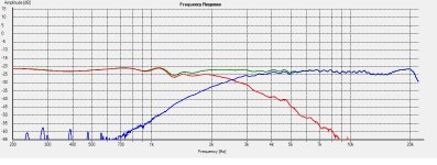
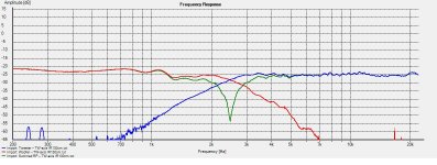
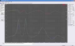
Frequency measurements:
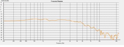
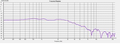
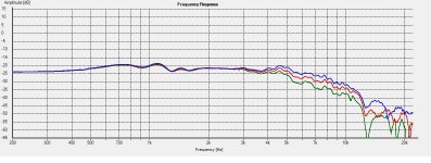
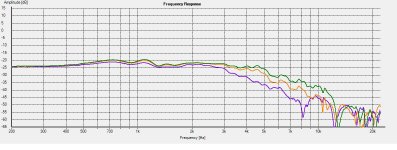
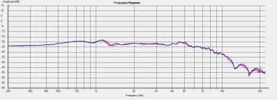
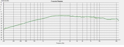
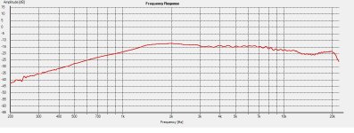
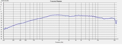
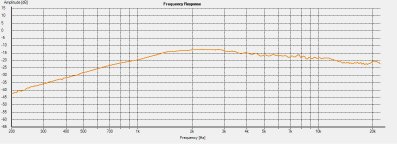
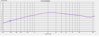
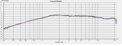
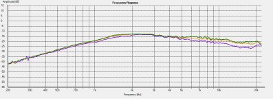
All measurements are done at tweeter height and at 1m distance. No frequency smoothing applied. Measurements are valid down to 250Hz.
Woofer:
Picture1: Tweeter-axis, 0 degrees.
Picture2: Tweeter-axis, 15 degrees.
Picture3: Tweeter-axis, 22.5 degrees.
Picture4: Tweeter-axis, 30 degrees.
Picture5: Tweeter-axis, 45 degrees.
Picture6: Tweeter-axis, 0, 15, 22.5 degrees combined.
Picture7: Tweeter-axis, 22.5, 30, 45 degrees combined.
Picture8: Tweeter-axis, 0 degrees, box 1L (blue) and 2R (red).
Comments:
Very smooth frequency response and roll-off. There is some raggedness between 800-1200Hz caused by most likely surround resonances and cone diffractions. No nasty cone break-up and a usable range up to 3000Hz with maintained power response and off-axis behavior. Good frequency consistency between the two driver units.
Attachments
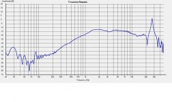
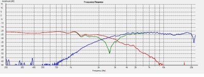
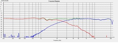
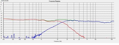
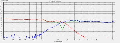
Frequency measurements:
All measurements are done at tweeter height and at 1m distance. No frequency smoothing applied. Measurements are valid down to 250Hz.
Tweeter:
Picture1: Tweeter-axis, 0 degrees.
Picture2: Tweeter-axis, 15 degrees.
Picture3: Tweeter-axis, 22.5 degrees.
Picture4: Tweeter-axis, 30 degrees.
Picture5: Tweeter-axis, 45 degrees.
Picture6: Tweeter-axis, 0, 15, 22.5 degrees combined.
Picture7: Tweeter-axis, 22.5, 30, 45 degrees combined.
Picture8: Tweeter-axis, 0 degrees, box 1L (blue) and 2R (red).
Picture9: Tweeter-axis, 0 degrees, cone break-up.
Comments:
Smooth frequency response and thanks to the DXT technology, crazy good off-axis frequency response and behavior. Nasty cone break-up at 27000Hz, but high enough in frequency to not cause a problem. Slight frequency dips between 3000-4000Hz caused by baffle diffraction and at 13000Hz caused by the DXT lens. Good frequency consistency between the two driver units.
Next, cross-over design and simulation….
Attachments
-
 Picture3.JPG108.4 KB · Views: 60
 -
 Picture2.JPG108.8 KB · Views: 123
 -
 Picture1.JPG109 KB · Views: 157
 -
 Picture4.JPG108 KB · Views: 46
 -
 Picture5.JPG109 KB · Views: 48
 -
 Picture6.JPG111.5 KB · Views: 90
 -
 Picture7.JPG112.3 KB · Views: 107
 -
 Picture8.JPG110.3 KB · Views: 105
 -
 Picture9.JPG127.3 KB · Views: 113
Yes, but that’s not my intention.")
I’m currently breaking them in and doing final measurements of the finished result. It’s a lot of pictures and diagrams to compile and write. It takes some time do and I’m also simultaneously building another design (this time some wood working).
Be patient I will continue as fast as I can.
I’m currently breaking them in and doing final measurements of the finished result. It’s a lot of pictures and diagrams to compile and write. It takes some time do and I’m also simultaneously building another design (this time some wood working).
Be patient I will continue as fast as I can.
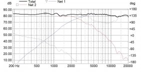
Cross-over design and simulation:
It’s time for some cross-over simulation. All diagrams are shown with an 80db scale and no frequency smoothing is applied.
Woofer:
There was no problem to achieve the target cross-over frequency of around 2500Hz for the woofer. The woofer has a very controlled and smooth roll-off. I choose an oversized inductor to get a BSC (baffle step compensation) of around 4.5db. The cross-over is a simple electrical 2nd order with only two components to achieve a 4th order target slope. See picture1.
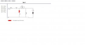
Tweeter:
This one was a different beast to tame I had to go through six different cross-over simulations to get what I wanted. It has about 10-12db higher sensitivity than the BSC compensated woofer and it's somewhat tricky to get the upper frequencies in place and at the same time get the phase interaction between the two driver units in place. R1051 is used to adjust the tweeter level, while at the same time keep the good phase integration between the two driver units and the desired impedance at place. See picture2. The cross-over is an electrical 3rd order with a couple of series resistor for attenuation to achieve a 4th order target slope.
Picture1: Woofer cross-over.
Picture2: Tweeter cross-over.
Picture3: Tweeter-axis, 0 degrees.
Picture4: Tweeter-axis, 0 degrees, reverse polarity.
Picture5: Tweeter-axis, 0 degrees, individual phase response.
Picture6: Tweeter-axis, 15 degrees.
Picture7: Tweeter-axis, 15 degrees, reverse polarity.
Picture8: Tweeter-axis, 15 degrees, individual phase response.
Picture9: Tweeter-axis, 22.5 degrees.
Picture10: Tweeter-axis, 22.5 degrees, reverse polarity.
Next, cross-over design and simulation continued….
It’s time for some cross-over simulation.
All diagrams are shown with an 80db scale and no frequency smoothing is applied.Woofer:
There was no problem to achieve the target cross-over frequency of around 2500Hz for the woofer. The woofer has a very controlled and smooth roll-off. I choose an oversized inductor to get a BSC (baffle step compensation) of around 4.5db. The cross-over is a simple electrical 2nd order with only two components to achieve a 4th order target slope. See picture1.
Tweeter:
This one was a different beast to tame
I had to go through six different cross-over simulations to get what I wanted. It has about 10-12db higher sensitivity than the BSC compensated woofer and it's somewhat tricky to get the upper frequencies in place and at the same time get the phase interaction between the two driver units in place. R1051 is used to adjust the tweeter level, while at the same time keep the good phase integration between the two driver units and the desired impedance at place. See picture2. The cross-over is an electrical 3rd order with a couple of series resistor for attenuation to achieve a 4th order target slope.Picture1: Woofer cross-over.
Picture2: Tweeter cross-over.
Picture3: Tweeter-axis, 0 degrees.
Picture4: Tweeter-axis, 0 degrees, reverse polarity.
Picture5: Tweeter-axis, 0 degrees, individual phase response.
Picture6: Tweeter-axis, 15 degrees.
Picture7: Tweeter-axis, 15 degrees, reverse polarity.
Picture8: Tweeter-axis, 15 degrees, individual phase response.
Picture9: Tweeter-axis, 22.5 degrees.
Picture10: Tweeter-axis, 22.5 degrees, reverse polarity.
Next, cross-over design and simulation continued….
Attachments
-
 Picture3.JPG143.7 KB · Views: 730
 -
 Picture2.JPG33.8 KB · Views: 742
 -
 Picture1.JPG30.7 KB · Views: 750
 -
 Picture4.JPG145.3 KB · Views: 707
 -
 Picture5.JPG112.5 KB · Views: 678
 -
 Picture6.JPG141.9 KB · Views: 89
 -
 Picture7.JPG142.9 KB · Views: 95
 -
 Picture8.JPG110.8 KB · Views: 74
 -
 Picture9.JPG142.5 KB · Views: 87
 -
 Picture10.JPG144.3 KB · Views: 93
Cross-over design and simulation continued:
Picture1: Tweeter-axis, 22.5 degrees, individual phase response.
Picture2: Tweeter-axis, 30 degrees.
Picture3: Tweeter-axis, 30 degrees, reverse polarity.
Picture4: Tweeter-axis, 30 degrees, individual phase response.
Picture5: Tweeter-axis, 45 degrees.
Picture6: Tweeter-axis, 45 degrees, reverse polarity.
Picture7: Tweeter-axis, 45 degrees, individual phase response.
Picture8: Tweeter-axis, 0, 15, 22.5, 30 and 45 degrees horizontal off-axis.
Picture9: Tweeter-axis, 15 degrees, tweeter level adjustment.
Picture10: System impedance.
Comments:
The cross-over is optimized for a listening angle between 15-30 degrees. Very good off-axis behaviour, power response and phase integration between the driver units. Picture10 show a 4 ohm minimum impedance around 3000Hz.
Next, system measurements of the finished speaker….
Attachments
-
 Picture3.JPG142.7 KB · Views: 52
 -
 Picture2.JPG141 KB · Views: 48
 -
 Picture1.JPG112 KB · Views: 68
 -
 Picture4.JPG111.7 KB · Views: 34
 -
 Picture5.JPG140.6 KB · Views: 39
 -
 Picture6.JPG142.4 KB · Views: 42
 -
 Picture7.JPG111.8 KB · Views: 27
 -
 Picture8.JPG128.4 KB · Views: 87
 -
 Picture9.JPG124.5 KB · Views: 82
 -
 Picture10.JPG155 KB · Views: 77
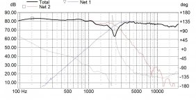
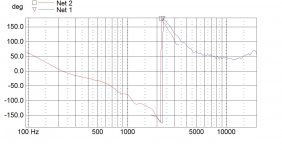
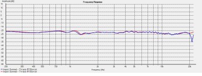
System measurements of the finished speaker:
I always listening a couple of days on the finished speakers before I do the final measurements so my listening impression isn’t influenced by my measurements. “The truth is what you hear, not what can you measure”
This is the actual measurements of the finished speakers. In my opinion these measurements are equally important as the raw driver measurements and it’s the tool to confirm if the simulations and what you are hearing is correct or not.
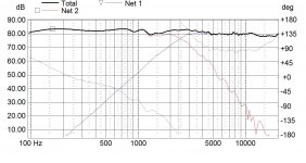
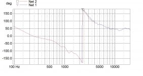
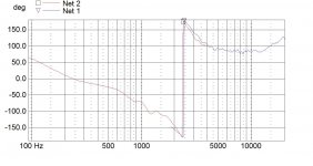
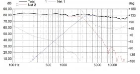
All diagrams are shown with an 80db scale and no frequency smoothing is applied.
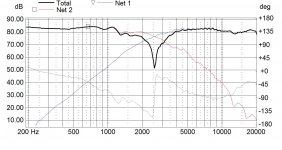
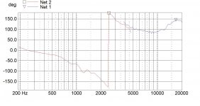
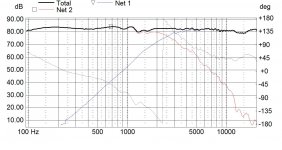
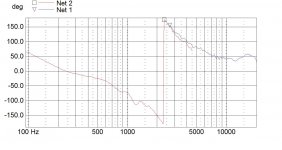
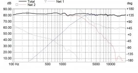
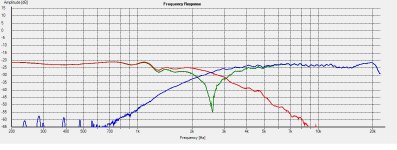
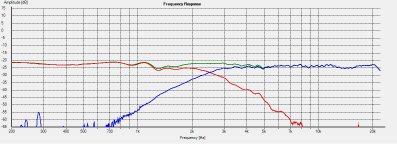
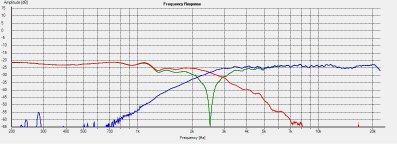
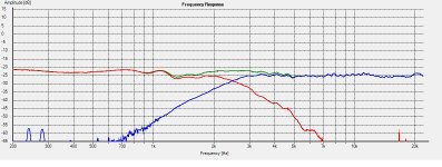
Picture1: Tweeter-axis, 0 degrees, summed and individual driver frequency response.
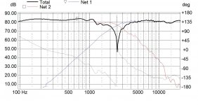
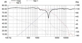
Picture2: Tweeter-axis, 0 degrees, reversed polarity and individual driver frequency response.
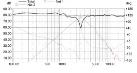
Picture3: Tweeter-axis, 15 degrees, summed and individual driver frequency response.
Picture4: Tweeter-axis, 0 degrees, reversed polarity and individual driver frequency response.
Picture5: Tweeter-axis, 22.5 degrees, summed and individual driver frequency response.
Picture6: Tweeter-axis, 22.5 degrees, reversed polarity and individual driver frequency response.
Picture7: Tweeter-axis, 30 degrees, summed and individual driver frequency response.
Picture8: Tweeter-axis, 30 degrees, reversed polarity and individual driver frequency response.
Picture9: Tweeter-axis, 45 degrees, summed and individual driver frequency response.
Picture10: Tweeter-axis, 45 degrees, reversed polarity and individual driver frequency response.
Comments:
They actually measure better than simulated. Look at the deep reverse null at the cross-over frequency. It indicates good phase interaction between the woofer and the tweeter.
Next, System measurements of the finished speaker continued….
I always listening a couple of days on the finished speakers before I do the final measurements so my listening impression isn’t influenced by my measurements. “The truth is what you hear, not what can you measure”
This is the actual measurements of the finished speakers. In my opinion these measurements are equally important as the raw driver measurements and it’s the tool to confirm if the simulations and what you are hearing is correct or not.
All diagrams are shown with an 80db scale and no frequency smoothing is applied.
Picture1: Tweeter-axis, 0 degrees, summed and individual driver frequency response.
Picture2: Tweeter-axis, 0 degrees, reversed polarity and individual driver frequency response.
Picture3: Tweeter-axis, 15 degrees, summed and individual driver frequency response.
Picture4: Tweeter-axis, 0 degrees, reversed polarity and individual driver frequency response.
Picture5: Tweeter-axis, 22.5 degrees, summed and individual driver frequency response.
Picture6: Tweeter-axis, 22.5 degrees, reversed polarity and individual driver frequency response.
Picture7: Tweeter-axis, 30 degrees, summed and individual driver frequency response.
Picture8: Tweeter-axis, 30 degrees, reversed polarity and individual driver frequency response.
Picture9: Tweeter-axis, 45 degrees, summed and individual driver frequency response.
Picture10: Tweeter-axis, 45 degrees, reversed polarity and individual driver frequency response.
Comments:
They actually measure better than simulated.
Look at the deep reverse null at the cross-over frequency. It indicates good phase interaction between the woofer and the tweeter.Next, System measurements of the finished speaker continued….
Attachments
-
 Picture3.JPG115 KB · Views: 78
 -
 Picture2.JPG117.1 KB · Views: 111
 -
 Picture1.JPG116.8 KB · Views: 126
 -
 Picture4.JPG115.8 KB · Views: 51
 -
 Picture5.JPG114.5 KB · Views: 42
 -
 Picture6.JPG115.6 KB · Views: 44
 -
 Picture7.JPG114.1 KB · Views: 48
 -
 Picture8.JPG117.8 KB · Views: 47
 -
 Picture9.JPG115.8 KB · Views: 59
 -
 Picture10.JPG116.3 KB · Views: 58
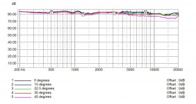
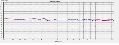
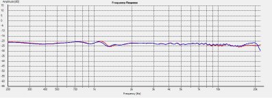
System measurements of the finished speaker continued:
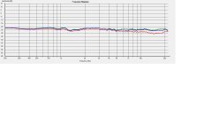
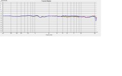
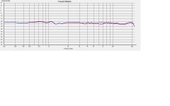
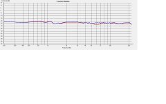
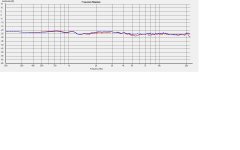
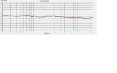
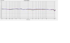
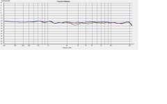
All diagrams are shown with an 80db scale and no frequency smoothing is applied, unless told so.
Picture1: Tweeter-axis, 0 (blue), 15 (red) and 22.5 (green) degrees, summed frequency response.
Picture2: Tweeter-axis, 22.5 (green), 30 (blue) and 45 (red) degrees, summed frequency response.
Picture3: Tweeter-axis, 0 degrees, summed frequency response, with (red) and without (blue) grill.
Picture4: Tweeter-axis, 15 degrees, summed frequency response, with (red) and without (blue) grill.
Picture5: Tweeter-axis, 22.5 degrees, summed frequency response, with (red) and without (blue) grill.
Picture6: Tweeter-axis, 30 degrees, summed frequency response, with (red) and without (blue) grill.
Picture7: Tweeter-axis, 45 degrees, summed frequency response, with (red) and without (blue) grill.
Picture8: Tweeter-axis, 0 degrees, 5 (blue), 10 (red) and 15 (green) degrees above tweeter (vertical) frequency response. 1/12 octave smoothing.
Picture9: Tweeter-axis, 0 degrees, 5 (blue), 10 (red) and 15 (green) below tweeter (vertical) frequency response. 1/12 octave smoothing.
Picture10: System Impedance 1L (blue) 2R (green).
Comments:
Look at the tweeters off-axis behaviour. Even the vertical off-axis response looks quite good. Listening above tweeter-axis is slightly better than below, but who is crawling on the floor when listening? The grill cloth isn’t that bad but, as always get rid of the grill when you doing some serious listening.
Next, Listening impressions….
All diagrams are shown with an 80db scale and no frequency smoothing is applied, unless told so.
Picture1: Tweeter-axis, 0 (blue), 15 (red) and 22.5 (green) degrees, summed frequency response.
Picture2: Tweeter-axis, 22.5 (green), 30 (blue) and 45 (red) degrees, summed frequency response.
Picture3: Tweeter-axis, 0 degrees, summed frequency response, with (red) and without (blue) grill.
Picture4: Tweeter-axis, 15 degrees, summed frequency response, with (red) and without (blue) grill.
Picture5: Tweeter-axis, 22.5 degrees, summed frequency response, with (red) and without (blue) grill.
Picture6: Tweeter-axis, 30 degrees, summed frequency response, with (red) and without (blue) grill.
Picture7: Tweeter-axis, 45 degrees, summed frequency response, with (red) and without (blue) grill.
Picture8: Tweeter-axis, 0 degrees, 5 (blue), 10 (red) and 15 (green) degrees above tweeter (vertical) frequency response. 1/12 octave smoothing.
Picture9: Tweeter-axis, 0 degrees, 5 (blue), 10 (red) and 15 (green) below tweeter (vertical) frequency response. 1/12 octave smoothing.
Picture10: System Impedance 1L (blue) 2R (green).
Comments:
Look at the tweeters off-axis behaviour.
Even the vertical off-axis response looks quite good. Listening above tweeter-axis is slightly better than below, but who is crawling on the floor when listening? The grill cloth isn’t that bad but, as always get rid of the grill when you doing some serious listening. Next, Listening impressions….
Attachments
-
 Picture3.JPG124.2 KB · Views: 49
 -
 Picture2.JPG124.9 KB · Views: 74
 -
 Picture1.JPG123.4 KB · Views: 90
 -
 Picture4.JPG123 KB · Views: 31
 -
 Picture5.JPG122.4 KB · Views: 24
 -
 Picture6.JPG122.5 KB · Views: 30
 -
 Picture7.JPG122.7 KB · Views: 37
 -
 Picture8.JPG122.6 KB · Views: 38
 -
 Picture9.JPG122.9 KB · Views: 45
 -
 Picture10.JPG174.9 KB · Views: 58
Listening impressions:
Before I describe the sound I need something to benchmark them against and in this case I have compared them to my SAL451 speaker and Zaphs SR71. The S551-DXT isn’t fully broken in yet so I might revise my opinion later on.
This is what I have earlier written about the SAL451 compared to the SR71:
SR71:
+ Higher sensitivity than SAL451.
+ Higher max SPL than SAL451.
+ Good imaging.
+ More and deeper low-frequency output than SAL451.
– A bit grainy highs.
– A bit too forward mids.
– Less forgiving on bad recordings.
SAL451:
+ Excellent imaging.
+ Deep and wide soundstage.
+ More 3-Dimensional and warm than SR71.
+ Airy and fluid highs.
– Less deep and powerful low-frequency output than SR71.
– Lower sensitivity and lower max SPL than SR71.
Ok, how does the SU551-DXT stack up to the competition?
SU551-DXT:
+ Excellent imaging.
+ Deep and wide soundstage.
+ More 3-Dimensional than SR71 and SAL451.
+ More, faster and deeper low-frequency output than both SAL451 and SR71.
+ Higher sensitivity than the SAL451.
+/- Very neutral highs.
– Missing some transparency compared to the SAL451.
– Missing some crispiness in the highs compared to both SAL451 and SR71.
It’s not easy to describe sound, but I hope you get the overall picture. They all sound good, but have their own strengths and weaknesses and sonic characteristics.
If I have to choose an overall favorite, I would choose the SAL451 for its transparency and warmth. If I want powerful bass, great dispersion at all frequencies and eliminate sweet-spot behavior, I would choose the SU551-DXT. You can actually stand up and move around in front of the speakers without the sound stage falling apart. That’s quite impressive. If I’m in the mood of something in between, the SR71 is my choice.
Although the SR71 is a nice design and sounds good, I think it has the potential to perform even better. I’m currently building my own version of it, the SR701. The main difference is a larger box volume and a bit wider baffle. In my opinion a 14liter box is way too small for the ER18RNX driver and it sounds a bit congested in such a small box. My new box will be around 19liters. Since the baffle dimensions aren’t exactly the same I have to revise the original SR71 cross-over, or build a completely new one. More on that in a later build “Thread”.
Disclaimer:
The listening impressions and opinions are mine and to some extent my friends. I’m aware that different people have different preferences and taste on how a loudspeaker should sound and reproduce music. The loudspeaker can also sound different when using another equipment setup etc.
When designing a speaker for your self you have the benefit to build in your own taste how it should sound, rather than using someone else’s design. That said, I doesn’t claim that my designs are better than the Zaph SR71, just different and suits my preferences better.
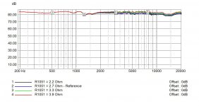
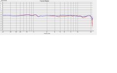
Additional measurements:
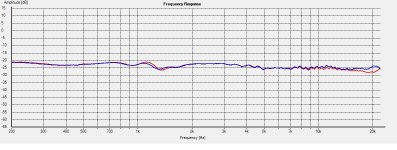
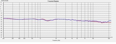
All diagrams are shown with an 80db scale and no frequency smoothing is applied.
Picture1: Tweeter-axis, 0 degrees, 1L (blue) + 2R (red) comparison
Picture2: Tweeter-axis, 15 degrees, 1L (blue) + 2R (red) comparison
Picture3: Tweeter-axis, 22.5 degrees, 1L (blue) + 2R (red) comparison
Picture4: Tweeter-axis, 30 degrees, 1L (blue) + 2R (red) comparison
Picture5: Tweeter-axis, 45 degrees, 1L (blue) + 2R (red) comparison
Comments:
Overall, very good conformity between the two loudspeakers. We have a slight difference in the absolute top end of the frequency response.
Next, summing up the SU551-DXT design….
Before I describe the sound I need something to benchmark them against and in this case I have compared them to my SAL451 speaker and Zaphs SR71. The S551-DXT isn’t fully broken in yet so I might revise my opinion later on.
This is what I have earlier written about the SAL451 compared to the SR71:
SR71:
+ Higher sensitivity than SAL451.
+ Higher max SPL than SAL451.
+ Good imaging.
+ More and deeper low-frequency output than SAL451.
– A bit grainy highs.
– A bit too forward mids.
– Less forgiving on bad recordings.
SAL451:
+ Excellent imaging.
+ Deep and wide soundstage.
+ More 3-Dimensional and warm than SR71.
+ Airy and fluid highs.
– Less deep and powerful low-frequency output than SR71.
– Lower sensitivity and lower max SPL than SR71.
Ok, how does the SU551-DXT stack up to the competition?
SU551-DXT:
+ Excellent imaging.
+ Deep and wide soundstage.
+ More 3-Dimensional than SR71 and SAL451.
+ More, faster and deeper low-frequency output than both SAL451 and SR71.
+ Higher sensitivity than the SAL451.
+/- Very neutral highs.
– Missing some transparency compared to the SAL451.
– Missing some crispiness in the highs compared to both SAL451 and SR71.
It’s not easy to describe sound, but I hope you get the overall picture. They all sound good, but have their own strengths and weaknesses and sonic characteristics.
If I have to choose an overall favorite, I would choose the SAL451 for its transparency and warmth. If I want powerful bass, great dispersion at all frequencies and eliminate sweet-spot behavior, I would choose the SU551-DXT. You can actually stand up and move around in front of the speakers without the sound stage falling apart. That’s quite impressive. If I’m in the mood of something in between, the SR71 is my choice.
Although the SR71 is a nice design and sounds good, I think it has the potential to perform even better. I’m currently building my own version of it, the SR701. The main difference is a larger box volume and a bit wider baffle. In my opinion a 14liter box is way too small for the ER18RNX driver and it sounds a bit congested in such a small box. My new box will be around 19liters. Since the baffle dimensions aren’t exactly the same I have to revise the original SR71 cross-over, or build a completely new one. More on that in a later build “Thread”.
Disclaimer:
The listening impressions and opinions are mine and to some extent my friends. I’m aware that different people have different preferences and taste on how a loudspeaker should sound and reproduce music. The loudspeaker can also sound different when using another equipment setup etc.
When designing a speaker for your self you have the benefit to build in your own taste how it should sound, rather than using someone else’s design. That said, I doesn’t claim that my designs are better than the Zaph SR71, just different and suits my preferences better.
Additional measurements:
All diagrams are shown with an 80db scale and no frequency smoothing is applied.
Picture1: Tweeter-axis, 0 degrees, 1L (blue) + 2R (red) comparison
Picture2: Tweeter-axis, 15 degrees, 1L (blue) + 2R (red) comparison
Picture3: Tweeter-axis, 22.5 degrees, 1L (blue) + 2R (red) comparison
Picture4: Tweeter-axis, 30 degrees, 1L (blue) + 2R (red) comparison
Picture5: Tweeter-axis, 45 degrees, 1L (blue) + 2R (red) comparison
Comments:
Overall, very good conformity between the two loudspeakers. We have a slight difference in the absolute top end of the frequency response.
Next, summing up the SU551-DXT design….
Attachments
Summing up the SU551-DXT design:
It’s time for summing the design up and I think I have accomplished my design goals.
The design goals that I set up when starting the project:
1. To use the Parts Express 14liter box “302-721s”.
2. Have a smooth system power response and off-axis frequency response.
3. Cross-over frequency around 2500 Hz.
4. Cross-over slopes, 4th order Linkwitz Riley, acoustical.
5. Bass extension down to low 40ies.
6. Simple crossover with standard component values.
7. Adjustable tweeter level.
Summation:
• I ended up with a port tuning of 44Hz (50x155mm) and I use foam plugs if want to use a closed box configuration. The port tuning of 44Hz is not that critical, it’s okay to go up or down a couple of Hz.
• Nice and even system power response, dispersion and great off-axis behavior.
• The “Baffle Step Compensation” I ended up with was roughly 4db.
• The final cross-over point I ended up with was around 2500-2550 Hz. Pretty close to the design goal
• The cross-over slopes I used where 24db/octave acoustically, 2nd order electrically for the woofer and 3rd order for the tweeter.
• These babies play a lot of bass, fast and deep. If you are a bass-oholic you might want to use a subwoofer from 50Hz and down.
• I think I ended up with a non-complex filter design. All components are standard values. I used air-core coils in the design and MKP type caps and MOX resistors.
• By replacing the R1051 resistor you can tune the tweeter level to your liking.
Loudspeaker setup:
As always you have to experiment with the loudspeaker setup to find the optimal loudspeaker placement for your room and listening distance. I use them roughly 60cm from back-wall and 2meters between them and at a listening distance between 2-2.5meters. I don’t use any toe-in. The loudspeaker performs optimal at a listening angle of 15-30 degrees. If you place them to close to the back-wall you can find them too bass heavy and I recommend using foam plugs or a closed box version instead.
I’m currently thinking of changing the R1051 resistor from 2.7 to 3.3 Ohm to get a bit higher tweeter level, but I think I will wait a couple of more weeks to let the loudspeakers break-in a bit further.
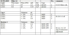
Cross-over parts list:
Use filter components of your own preferences. I recommend using components with +/- 5% tolerance or better and of MKP type. I personally use Mcap Audiophiler MKP +/- 3% caps. These caps often have a tolerance of +/- 1% and have in my opinion a very neutral sound and are not expensive. See Picture1. The resistor R1051 can be changed to adjust the desired tweeter level.
Picture1: Cross-over parts list.
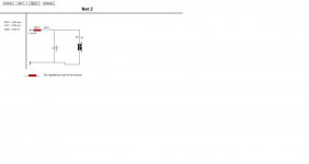
Picture2: Woofer cross-over section.
Picture3: Tweeter cross-over section.
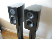
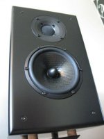
Picture4: Picture of the SU551-DXT loudspeaker next to the Zaph SR71.
Picture5: Picture of the SU551-DXT loudspeaker.
I need your help!
I need your help to decide which drivers to use in the next design I’m going to build. First I’m going to build my own version of the Zaph SR71 as I described in an earlier post, but I really need some suggestions on what to do next. Here are some ideas I have, but haven’t decided on yet:
1. SU551 with the Fountek JP3 ribbon driver instead of the DXT tweeter.
2. 2.5-way version of the SU551-DXT.
3. An Excel version of the “SE551-DXT” with the W16NX woofer and the DXT tweeter or another tweeter?
4. SEAS U18RNX/P and some tweeter?
I have the following tweeters at my disposal:
• SEAS 27TDFC (H1189)
• SEAS 27TBFC/G (H1212)
• SEAS 27TBCD/GB-DXT (H1499)
• Fountek JP3.0MB
• Fountek NeoCD3.5H
I’m having some interest in these two tweeters and am considering buying them:
• Scan-Speak D3004/602010
• SB-Acoustics SB29RDC-C000-4
Does anyone have experience with any of these tweeters? As for the woofers it must be a SEAS driver from the 15, 16 or 18cm Prestige/Excel product range.
Any suggestion is appreciated.
Thanks
/Goran
It’s time for summing the design up and I think I have accomplished my design goals.
The design goals that I set up when starting the project:
1. To use the Parts Express 14liter box “302-721s”.
2. Have a smooth system power response and off-axis frequency response.
3. Cross-over frequency around 2500 Hz.
4. Cross-over slopes, 4th order Linkwitz Riley, acoustical.
5. Bass extension down to low 40ies.
6. Simple crossover with standard component values.
7. Adjustable tweeter level.
Summation:
• I ended up with a port tuning of 44Hz (50x155mm) and I use foam plugs if want to use a closed box configuration. The port tuning of 44Hz is not that critical, it’s okay to go up or down a couple of Hz.
• Nice and even system power response, dispersion and great off-axis behavior.
• The “Baffle Step Compensation” I ended up with was roughly 4db.
• The final cross-over point I ended up with was around 2500-2550 Hz. Pretty close to the design goal
• The cross-over slopes I used where 24db/octave acoustically, 2nd order electrically for the woofer and 3rd order for the tweeter.
• These babies play a lot of bass, fast and deep. If you are a bass-oholic you might want to use a subwoofer from 50Hz and down.
• I think I ended up with a non-complex filter design. All components are standard values. I used air-core coils in the design and MKP type caps and MOX resistors.
• By replacing the R1051 resistor you can tune the tweeter level to your liking.
Loudspeaker setup:
As always you have to experiment with the loudspeaker setup to find the optimal loudspeaker placement for your room and listening distance. I use them roughly 60cm from back-wall and 2meters between them and at a listening distance between 2-2.5meters. I don’t use any toe-in. The loudspeaker performs optimal at a listening angle of 15-30 degrees. If you place them to close to the back-wall you can find them too bass heavy and I recommend using foam plugs or a closed box version instead.
I’m currently thinking of changing the R1051 resistor from 2.7 to 3.3 Ohm to get a bit higher tweeter level, but I think I will wait a couple of more weeks to let the loudspeakers break-in a bit further.
Cross-over parts list:
Use filter components of your own preferences. I recommend using components with +/- 5% tolerance or better and of MKP type. I personally use Mcap Audiophiler MKP +/- 3% caps. These caps often have a tolerance of +/- 1% and have in my opinion a very neutral sound and are not expensive. See Picture1. The resistor R1051 can be changed to adjust the desired tweeter level.
Picture1: Cross-over parts list.
Picture2: Woofer cross-over section.
Picture3: Tweeter cross-over section.
Picture4: Picture of the SU551-DXT loudspeaker next to the Zaph SR71.
Picture5: Picture of the SU551-DXT loudspeaker.
I need your help!
I need your help to decide which drivers to use in the next design I’m going to build. First I’m going to build my own version of the Zaph SR71 as I described in an earlier post, but I really need some suggestions on what to do next. Here are some ideas I have, but haven’t decided on yet:
1. SU551 with the Fountek JP3 ribbon driver instead of the DXT tweeter.
2. 2.5-way version of the SU551-DXT.
3. An Excel version of the “SE551-DXT” with the W16NX woofer and the DXT tweeter or another tweeter?
4. SEAS U18RNX/P and some tweeter?
I have the following tweeters at my disposal:
• SEAS 27TDFC (H1189)
• SEAS 27TBFC/G (H1212)
• SEAS 27TBCD/GB-DXT (H1499)
• Fountek JP3.0MB
• Fountek NeoCD3.5H
I’m having some interest in these two tweeters and am considering buying them:
• Scan-Speak D3004/602010
• SB-Acoustics SB29RDC-C000-4
Does anyone have experience with any of these tweeters? As for the woofers it must be a SEAS driver from the 15, 16 or 18cm Prestige/Excel product range.
Any suggestion is appreciated.
Thanks
/Goran
Attachments

Hello Goran,
Congratulations! I enjoyed following your speaker project on this thread. There aren't very many well documented designs out there to begin with. One question, how did you come up with the crossover frequency? Was it before or after you measured the tweeter/woofer response?
Congratulations! I enjoyed following your speaker project on this thread. There aren't very many well documented designs out there to begin with. One question, how did you come up with the crossover frequency? Was it before or after you measured the tweeter/woofer response?
Hi Ultrakaz,
Thank you. To answer your question - both actually. The 2500Hz cross-over frequency was just an estimate based on manufacturer specs and what other people have measured, like Zaph, Mark K etc. My own measurements in the actual baffle just confirmed it to be a suitable cross-over frequency. Both drivers operate within its pass-band and well out of any distortion frequency limits. The DXT tweeter can be crossed over at much lower range and the woofer has a very good dispersion up to almost 3000Hz and without any nasty cone break-ups. In fact much better than the manufacturer spec. Therefore a choose something in between.
I’ve been looking a long time for a woofer that can be crossed over a bit higher than usual in the area of 2.8-3kHz to mate with a ribbon tweeter like the Fountek and without scarifying any bass-output. With the SEAS U16RCY/P I think I have found it. The bass from this small woofers is incredible, fast and punchy.
/Goran
Thank you. To answer your question - both actually. The 2500Hz cross-over frequency was just an estimate based on manufacturer specs and what other people have measured, like Zaph, Mark K etc. My own measurements in the actual baffle just confirmed it to be a suitable cross-over frequency. Both drivers operate within its pass-band and well out of any distortion frequency limits. The DXT tweeter can be crossed over at much lower range and the woofer has a very good dispersion up to almost 3000Hz and without any nasty cone break-ups. In fact much better than the manufacturer spec. Therefore a choose something in between.
I’ve been looking a long time for a woofer that can be crossed over a bit higher than usual in the area of 2.8-3kHz to mate with a ribbon tweeter like the Fountek and without scarifying any bass-output. With the SEAS U16RCY/P I think I have found it.
The bass from this small woofers is incredible, fast and punchy./Goran
SU551-DXT:
+ Excellent imaging.
+ Deep and wide soundstage.
+ More 3-Dimensional than SR71 and SAL451.
+ More, faster and deeper low-frequency output than both SAL451 and SR71.
+ Higher sensitivity than the SAL451.
+/- Very neutral highs.
– Missing some transparency compared to the SAL451.
– Missing some crispiness in the highs compared to both SAL451 and SR71.
Hello Goran,
Good to hear that the DXT can be crossed lower....
I asked about the crossover frequency because of your comments on SU551 "missing some transparency...and crispness in the highs" and was wondering if a lower crossover point would make it more transparent. I'm sure you might be giving up some ultimate spl, but it is a two-way afterall. The two-ways that I have heard with <1400Hz crossovers seem to sound more "open."
- Status
- This old topic is closed. If you want to reopen this topic, contact a moderator using the "Report Post" button.
- Home
- Loudspeakers
- Multi-Way
- SU551-DXT --2-way speaker