sr800
hello sir mile, when you will share scheme SR800? I'm waiting for the discussion
DC protect with triac, zobel network, thermal protect with NTC, VI limiter and TEF output stage add. DC servo removed, CCS for input pair work with 3mA instead 1mA (SR50, 100, 200). Rail voltage +/-95V dc.
Regards
hello sir mile, when you will share scheme SR800? I'm waiting for the discussion
sr800

When Mr Mile?hello sir mile, when you will share scheme SR800? I'm waiting for the discussion
Scrub triac dc protection as peavey used this idea and it wasted lots of out puts when it fired thus s/c whole out put stage.. Add relay dc as this will save speaker plus out puts being duffed up..
I've always used dc/ dectection with relay and designed many of these circuits such safe power down if amp out put is shorted thus cutting the said channel and keeping the good side up and running.
I've always used dc/ dectection with relay and designed many of these circuits such safe power down if amp out put is shorted thus cutting the said channel and keeping the good side up and running.
Can I use mj15024/15025 in place of 2sc5200/2sa1943.Also have some mje340/350 s can those be used in place of bd241c/242c.In the power supply in post 12 I know the mj15024/25 are to-3 but got 3 of each laying around and heatsinks to match.
MJ15024/15025 can be use instead 2SA1943/2SC5200 but MJE340/350 can't be use instead BD241C/242C, use some TO220 transistors like MJ15030/15031 or TIP31C/32C...
yepp.!! my apex SR200 has completed
using with supply 45-0-45vac 625VA torodial transformer 10,000uf / 100v * 6
apex sir is that 18pf from Q2 base to Q9 collector is important.?
and how much bias current should be adjusted
[URL=http://imageshack.us/photo/my-images/585/fo9u.jpg/][IMGDEAD]http://img585.imageshack.us/img585/2649/fo9u.jpg[/IMGDEAD][/URL]
Uploaded with [URL=http://imageshack.us]ImageShack.us[/URL]
What supply voltages are you using
I would increase the size of the two small to220 heat sinks.
The one on the right can get quite warm with such a small sink imo.
The small orange electrolytic caps seem small for pcb footprint, what value and voltage rating are they.
I would increase the size of the two small to220 heat sinks.
The one on the right can get quite warm with such a small sink imo.
The small orange electrolytic caps seem small for pcb footprint, what value and voltage rating are they.
Last edited:
What supply voltages are you using
I would increase the size of the two small to220 heat sinks.
The one on the right can get quite warm with such a small sink imo.
The small orange electrolytic caps seem small for pcb footprint, what value and voltage rating are they.
i am using 45-0-45 Vac / 625VA transformer with 30,000uf per voltage rail
i will replace the heatsinks to220
small orange caps are 2.2uf / 160V
yepp.!! my apex SR200 has completed
using with supply 45-0-45vac 625VA torodial transformer 10,000uf / 100v * 6
apex sir is that 18pf from Q2 base to Q9 collector is important.?
and how much bias current should be adjusted
[URL=http://imageshack.us/photo/my-images/585/fo9u.jpg/][IMGDEAD]http://img585.imageshack.us/img585/2649/fo9u.jpg[/IMGDEAD][/URL]
Uploaded with [URL=http://imageshack.us]ImageShack.us[/URL]
Nice work, set 8mV on 0.33R/5W resistors ( 25mA per output 100mA total).
18pF is important for amp stability with this PCB, I don't need it on my PCB.
Regards
It's have Miller input compensation cap.
Without this cap, the amp may have oscillation.
Have two ways compensated this amp,
1. Miller Compensation MC standart.
2. Miller Input Compensation MIC.
I have tried, the result is very good, no oscilltation with MIC 22pF and 10pF MC. Bob Cordel's book said MIC don't limit slew rete like MC, so, i chose MIC.
My amp look like this amp (SR200), but IPS & VAS cascoded with JFET (2SK170 & 2SJ75) and the current mirror is compensation transistor type.
It's have Miller input compensation cap.
Without this cap, the amp may have oscillation.
Have two ways compensated this amp,
1. Miller Compensation MC standart.
2. Miller Input Compensation MIC.
I have tried, the result is very good, no oscilltation with MIC 22pF and 10pF MC. Bob Cordel's book said MIC don't limit slew rete like MC, so, i chose MIC.
My amp look like this amp (SR200), but IPS & VAS cascoded with JFET (2SK170 & 2SJ75) and the current mirror is compensation transistor type.
Regards, can you post circuit of your amp?
Nice work, set 8mV on 0.33R/5W resistors ( 25mA per output 100mA total).
18pF is important for amp stability with this PCB, I don't need it on my PCB.
Regards
Hi Sir Mile, may we see your board?
I want to know how it looks, or just give some clue the good placement that must be used...
Thanks
Hi Walkalone, we are waitingIt's have Miller input compensation cap.
Without this cap, the amp may have oscillation.
Have two ways compensated this amp,
1. Miller Compensation MC standart.
2. Miller Input Compensation MIC.
I have tried, the result is very good, no oscilltation with MIC 22pF and 10pF MC. Bob Cordel's book said MIC don't limit slew rete like MC, so, i chose MIC.
My amp look like this amp (SR200), but IPS & VAS cascoded with JFET (2SK170 & 2SJ75) and the current mirror is compensation transistor type.
I hope only use 2SK170 or any easy available jfet, the 2SJ74 is not easy to get. But the good news is we can buy the replacement at diyAudio store: LSJ74
LSK170
but the price is quite high
(for me at least)Regards
I use only SR800 pcb for all SR amplifiers, and DC protect with triac was integrated on it also zobel network and fuses. FET instead BJT for LTP can be used without changes, I suggest 2SK117.
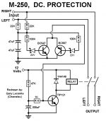
apex sir can i use this diagram
Attachments
apex sir can i use this diagram
Use speaker terminal from this thread, there is zobel and DC protect with triac on it or use protect from BA1000, AX11...
SR800
We are waiting for this SR800!
I use only SR800 pcb for all SR amplifiers, and DC protect with triac was integrated on it also zobel network and fuses. FET instead BJT for LTP can be used without changes, I suggest 2SK117.
We are waiting for this SR800!
Shr,
have you calculated currents for that relay driver circuit?
The tip is supposed to be a switch. How much base current does it need to become saturated, so that it can act as a switch?
The BC transistors will have a Vce that is very low.
Again, have you looked at what base current the detector transistors need to operate with low Vce?
- Home
- Amplifiers
- Solid State
- Studio Reference Amplifier