Pay attention to what Jane said above - GOOD advise.
.
I had some communication with the Hammond Application Engineers about the 125ESE.
They stated:
The 125xSE range was not intended for HiFi Applications, the problem being limited primary inductance, HOWEVER, very good results can be obtained by driving them with a tube with low rp or a tube in triode mode (which gives low rp).
I was particularly asking about using the 125ESE driven by a triode strapped EL34. My question to them was about what would happen if I exceeded the 80mA idle current rating and had 100mA idle instead. The response was that you would loose some of the primary inductance but since I was driving it with a triode strapped EL34 the reduced rp would more than make up for the primary inductance loss.
My experience suported that advise from Hammond.
I see that you are heading for a triode strapped EL34 as well - don't forget to add a 150R resistor in the screen to anode strap.
I have since started a "Super Champ" Guitar Amp build with a 125ESE driven by an 845 (approx 850V for 20W out).
Cheers,
Ian
Yep, I will heed those words. The 125FSE is actually bigger than I expected, I wonder how all those Chinese amps with smaller irons manage to get any bass out. But does anyone actually have any numbers on the primary inductance of the Hammond 125xSE -series? I didn't manage to find anything on these!
I noted with my spud amp - a single E55L per channel - that the 125ESE gave about 2W out before saturation was seen at 20Hz, but that tube has a very low RP around 550 ohms. Still, not bad for a "not made for Hi-Fi" tranny... Suffice to say, I was very positively surprised by the performance.
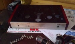
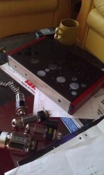
Below some photos of the chassis parts. I've been busy building this the last week and a half. I remember I had something more important to do than this, but for some odd reason I really don't care right now...
Attachments
It's worth remembering that the rp of triode outputs is only an expression of the internal feedback term that's conceptually obscured by an unfortunate choice of language. rp is simply the reciprocal of the plate to cathode transconductance, the feedback. Although negative feedback improves small signal frequency response and damping, it (lower rp) does nothing at all to solve the problem of low inductive reactance shunting output current, robbing power and driving the OPT core towards saturation. Negative feedback does tend to hide the distortion from saturation in small amounts. Metering the current going into a class AB stage while lowering the frequency and maintaining constant output power will show a revealing rise.
The notion that triodes put out less power than pentodes and need a lower impedance from the OPT is a flawed one, based mainly on the assumption that drive isn't increased to maintain current when there's more feedback (lower rp). But there needn't be a ceiling at zero bias on the control grid, it can be driven into class 2. And when that it done, the output transformer turns/impedance ratio needn't be any different for triodes than it is for pentodes running on the same supply voltage and driven to the same peak currents. Using a lower transformer load impedance on a triode is just a half baked way to try to reduce the feedback, by reducing the plate voltage swing, leading to less cancellation of the drive current which effectively means more drive. Join the ranks of people using robust drivers, and cower from rp no more! Ultra-linear also needn't suffer any power penalty.
Expecting a different transformer requirement with feedback is just as invalid as expecting a car to need to be in a different gear just because the cruise-control is on.
Don't let feedback fool anyone into thinking their output transformers are somehow better. The 3 dB down power point is where the inductive reactance equals the transformed load impedance (turns ratio squared times 8 Ohms or whatever the output load is). It has nothing to do with rp.
... I wonder how all those Chinese amps with smaller irons manage to get any bass out.
The thing that rescues people a bit when using miserable output transformers is the rising impedance of their speaker systems near bass resonance. While available output current is being robbed by the shunt inductance, less current swing is required to get rated voltage (or closer to it) with that rising load impedance. Note that the measured power response into a higher load would show roll-off that's even worse than that into the rated load. Although an amp may not be going into clipping in the low end, there is still degraded low end distortion since the output valves see more gm shift as they struggle putting out a higher current swing than would otherwise be required, since less of what they produce contributes power to the external load.
Ironically, an amp with a weak output transformer pairs better with cheaper/smaller speakers than good ones since the former generally have the bass resonance at a higher frequency. The perceived acoustic power in that range exceeds what one would expect from the declining (into a resistive load) measured amp capability.
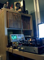
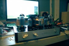
Well, so it seems that being stuck with the output tube choice is over. An amplifier is born! The draft schematic I posted earlier made itself to be an amp, and surprisingly enough, it worked as I thought it out from the start! 350V on the EL34's plates. It's late, though, so I'm not blasting this out on the Big Baffles, but at least it's making sounds and the voltages are reading what I wanted them to. I measured about 4W into 4 ohms (didn't have an 8 ohm dummy around) before clipping. Not stellar, but it's got a 5K load...
Attachments
- Status
- This old topic is closed. If you want to reopen this topic, contact a moderator using the "Report Post" button.