It suddenly struck me; it seems as in you have a capacitor in series with the tweeter. That could, in combination with tweeter resonance caus a bit of a dip just above the resonance. It should not vary between baffles of course, but I see a bit of a tendency to a dip even in the better baffles. Possibly.
What value does the cap have?
What value does the cap have?
In case anybody is curious here are the results of the baffle extenstion and felt tests ...
I have been trying Edge and frd's BDS to correlate with my measurements but I am not having much success in that regard. I admit my 'newbness' is probably a big factor here. It seems I do have a solution based on the test a few posts up but I would like to understand why.
An externally hosted image should be here but it was not working when we last tested it.
An externally hosted image should be here but it was not working when we last tested it.
I have been trying Edge and frd's BDS to correlate with my measurements but I am not having much success in that regard. I admit my 'newbness' is probably a big factor here. It seems I do have a solution based on the test a few posts up but I would like to understand why.
Svante said:It suddenly struck me; it seems as in you have a capacitor in series with the tweeter. That could, in combination with tweeter resonance caus a bit of a dip just above the resonance. It should not vary between baffles of course, but I see a bit of a tendency to a dip even in the better baffles. Possibly.
What value does the cap have?
The value is 30uf. Figuring in the resistance of the wire and referencing the impedance measurements. I calculated roughly a crossover ~700 Hz. The resonance of the tweeter according to Accuton is 350Hz.
Thanks for sticking with me. I would like to understand it.
ttruman said:
The value is 30uf. Figuring in the resistance of the wire and referencing the impedance measurements. I calculated roughly a crossover ~700 Hz. The resonance of the tweeter according to Accuton is 350Hz.
Thanks for sticking with me. I would like to understand it.
Ah, oh so that "dip" due to the cap I was talking about would occur at ~500 Hz then, so that is not the explanation.
Still puzzled over this one
Looking over all of the measurements and running a quick-n-dirty test with an approximation of the driver dimensions (not quite sure what they are precisely), I'm wondering if the dip is inherent in the driver. I say this because if you look at a "baffle" response of the driver alone simulated in The Edge, the step of the diffraction signature at roughly 2.5K seems to overlay the dip on larger baffles. This step should normally be seen as a peak if the driver's native response is flat. A tweeter such as this one should be flat at 2.5K.
The various baffles alter the diffraction signature, moving the step down vs. the raw driver with various other diffraction undulations being changed as well. Moving the step down would let the native driver response start to become apparent again.
The step is usually fairly distinct and no a high-Q anomoly, but I'm still not convinced that there isn't an issue with the windowing of the impulse response. Any good measurement system requires the start time marker to be only a few sample points prior to the peak. Go back any farther and you introduce noise, that being the ambient room noise. It's inescapable. If you can't place the start time marker somewhere around 7.4ms for the impulse shown, something's wrong with the measurement setup or in SW itself. I doubt the latter, so more investigation of the setup is warranted, I think.
Dave
ttruman said:In case anybody is curious here are the results of the baffle extenstion and felt tests ...
An externally hosted image should be here but it was not working when we last tested it.
An externally hosted image should be here but it was not working when we last tested it.
I have been trying Edge and frd's BDS to correlate with my measurements but I am not having much success in that regard. I admit my 'newbness' is probably a big factor here. It seems I do have a solution based on the test a few posts up but I would like to understand why.
Looking over all of the measurements and running a quick-n-dirty test with an approximation of the driver dimensions (not quite sure what they are precisely), I'm wondering if the dip is inherent in the driver. I say this because if you look at a "baffle" response of the driver alone simulated in The Edge, the step of the diffraction signature at roughly 2.5K seems to overlay the dip on larger baffles. This step should normally be seen as a peak if the driver's native response is flat. A tweeter such as this one should be flat at 2.5K.
The various baffles alter the diffraction signature, moving the step down vs. the raw driver with various other diffraction undulations being changed as well. Moving the step down would let the native driver response start to become apparent again.
The step is usually fairly distinct and no a high-Q anomoly, but I'm still not convinced that there isn't an issue with the windowing of the impulse response. Any good measurement system requires the start time marker to be only a few sample points prior to the peak. Go back any farther and you introduce noise, that being the ambient room noise. It's inescapable. If you can't place the start time marker somewhere around 7.4ms for the impulse shown, something's wrong with the measurement setup or in SW itself. I doubt the latter, so more investigation of the setup is warranted, I think.
Dave
Re: Still puzzled over this one
Indeed my first thought was the same. The last measurements with the extended baffle seems to say so. Yet the earlier measurements with the free driver says it is not so. So doing a simulation on the three last baffle geometriesreveal that the difference SHOULD not be that large. Rather counter-intuitive, but it seems so.
...which leads to another question for ttruman (maybe I missed it and you already wrote it). Is it the very same driver that you measured in free space, the cardboard baffles, and in the real box? Or do you have two drivers, of which one may be damaged?
dlr said:
Looking over all of the measurements and running a quick-n-dirty test with an approximation of the driver dimensions (not quite sure what they are precisely), I'm wondering if the dip is inherent in the driver.
Indeed my first thought was the same. The last measurements with the extended baffle seems to say so. Yet the earlier measurements with the free driver says it is not so. So doing a simulation on the three last baffle geometriesreveal that the difference SHOULD not be that large. Rather counter-intuitive, but it seems so.
An externally hosted image should be here but it was not working when we last tested it.
...which leads to another question for ttruman (maybe I missed it and you already wrote it). Is it the very same driver that you measured in free space, the cardboard baffles, and in the real box? Or do you have two drivers, of which one may be damaged?
Re: Re: Still puzzled over this one
When I first encountered this, I thought it might be isolated to the single driver I was testing. So I tested four distinct C-23's and they all exhibited the same anomaly. That's when I started this thread and posted the first chart. Starting at Post #34 I decided to use one tweeter for all the posted test results; serial C23-6051251b. Post# 35 used an enclosure baseline from another tweeter because I started with the cardboard baffle testing. Post# 36 I established a new enclosure baseline using serial C23-6051251b; and that was used for the remaining comparisons.
The one thing I cannot explain fully is why the dip baseline from Post# 35 is only ~12db compared to ~15db of the new baseline starting at post #38. I believe that is because that baseline used in post #35 was not measured under the controlled circumstances of the new baseline. The new measurements below validates that believe.
For a sanity check I decided to run the free air and enclosure measurements side by side using serial C23-6051251b. First I ran the free air. Then the tweeter in the enclosure baffle. Then again with the enclosure tilted forward 6 deg. This was to offset the 6 deg tilt designed into the baffle. All at one meter.
I then ran the test again using another tweeter sample; serial C23-6051254a.
I hope this proves that both samples are broken ...
Svante said:...which leads to another question for ttruman (maybe I missed it and you already wrote it). Is it the very same driver that you measured in free space, the cardboard baffles, and in the real box? Or do you have two drivers, of which one may be damaged?
When I first encountered this, I thought it might be isolated to the single driver I was testing. So I tested four distinct C-23's and they all exhibited the same anomaly. That's when I started this thread and posted the first chart. Starting at Post #34 I decided to use one tweeter for all the posted test results; serial C23-6051251b. Post# 35 used an enclosure baseline from another tweeter because I started with the cardboard baffle testing. Post# 36 I established a new enclosure baseline using serial C23-6051251b; and that was used for the remaining comparisons.
The one thing I cannot explain fully is why the dip baseline from Post# 35 is only ~12db compared to ~15db of the new baseline starting at post #38. I believe that is because that baseline used in post #35 was not measured under the controlled circumstances of the new baseline. The new measurements below validates that believe.
For a sanity check I decided to run the free air and enclosure measurements side by side using serial C23-6051251b. First I ran the free air. Then the tweeter in the enclosure baffle. Then again with the enclosure tilted forward 6 deg. This was to offset the 6 deg tilt designed into the baffle. All at one meter.
An externally hosted image should be here but it was not working when we last tested it.
I then ran the test again using another tweeter sample; serial C23-6051254a.
An externally hosted image should be here but it was not working when we last tested it.
I hope this proves that both samples are broken ...
Ok, look at the free air response: it has a dip around 6 kHz, which makes sense since the driver is a bit less than half the width of your baffle which has a problem around 2.3 kHz.
In a more practical vein, try placing the driver center about 7.7 cm from the top of the baffle, 9.7 cm from one side, and 11.3 cm from the other side. That corresponds to alternative a from my previous post, and it might solve some of your problems.
In a more practical vein, try placing the driver center about 7.7 cm from the top of the baffle, 9.7 cm from one side, and 11.3 cm from the other side. That corresponds to alternative a from my previous post, and it might solve some of your problems.
DSP_Geek said:In a more practical vein, try placing the driver center about 7.7 cm from the top of the baffle, 9.7 cm from one side, and 11.3 cm from the other side. That corresponds to alternative a from my previous post, and it might solve some of your problems.
Sorry Geek, I am doing my best to keep up with everything. These tests are keeping me up very late. I created a new cardboard baffle with your dimensions. First I took a new free air. Then measured the cb baffle that matched my enclosure. Then the new cb baffle with your dimensions.
An externally hosted image should be here but it was not working when we last tested it.
It is an improvement but keep in mind the cb baffle does not dip nearly as bad as the enclosure.
Inductor said:2K5Hz - 3KHz dip x 1/4Wavelength
= 14 or 12cm Wavelength
= 3.5 or 3 cm.
Problem at this distance, possible size of inverted dome and possible cancellation in axis. Try measuring at 10 degrees angle. Also try with a net/difusor in front of the driver for sound radiation.
Inductor...your up....
First setup and measured baseline, then with diffuser, then rotated 15deg. (used rig as referance...only had 15 and 30 deg marks)
An externally hosted image should be here but it was not working when we last tested it.
Have impedance...
An externally hosted image should be here but it was not working when we last tested it.
Something to consider
The tweeter on the box is equidistant to three sides. That can be modeled to show an approximate diffraction signature for the box and will be exacerbated by the equal distances. However, one thing that you can't model is the diffraction from the driver below the tweeter.
I've measured more than 2db of diffraction in some instances, the worse being a hard coned midwoofer, the Accuton C95. Put a flat cover, cardboard should do fine, over the nearest driver (and successive ones if you wish) and re-measure taking care not to damage the surrounds. You may be surprised at just how much is related to adjacent drivers. I'm curious to see the difference.
The only solution to this problem will be to place felt in between the tweeter and the adjacent driver. This is a must for anything I do. Of course, I always do the additional felt all around the tweeter, but at least just in between drivers is less aesthetically displeasing.
ttruman said:
It is an improvement but keep in mind the cb baffle does not dip nearly as bad as the enclosure.
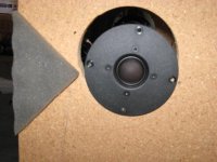
It's a start. Now try cutting right angle triangles from that felt and placing them on the baffle edges, with the 90 degree angle pointing at the tweeter, like so:
Attachments
ttruman said:I will get around to the lastest suggestions soon. I need to get some sleep tonight!
NO! NO SLEEP! Ninja speaker designers have no need for sleep!
 I wish my employer agreed!
Hi Charles,phase_accurate said:What happens with this dip off - axis ?
Regards
Charles
Thanks for joining in. Here is the results of the off axis...
An externally hosted image should be here but it was not working when we last tested it.
If I am not mistaken this is similar to what Dan (owdi) encountered. I believe this strengthens the baffle diffraction argument?
- Status
- This old topic is closed. If you want to reopen this topic, contact a moderator using the "Report Post" button.
- Home
- Loudspeakers
- Multi-Way
- Stuck in a dip