Good luck with that
I am a little worried about creating DC in a sense but with the way alternating current works it might work. It is a slight bit beyond my knowledge of experience but from a basic principle of things it makes sense.
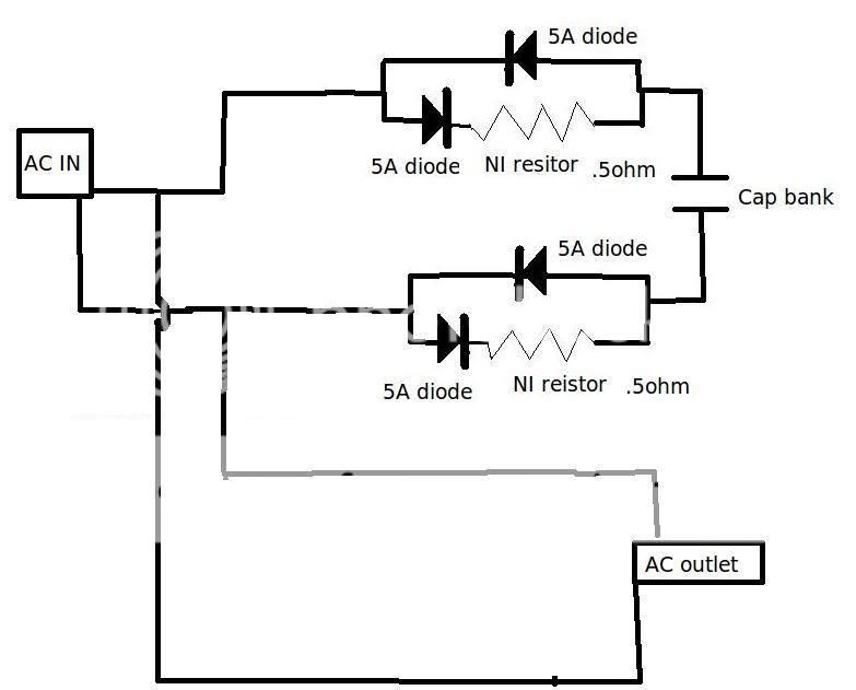
The diodes make is so all current draw goes through the NIR (non-inductive resistors) but only after attenuation. The other two on the bypass prevent draw from occurring not through the resistors. Obviously I will need to try with and without in order to get a measurement from an oscilloscope by probing different locations. The listening test is best though funny enough - once confirmed I am not producing anything I do not want. The reason is that the way the load works on the attenuation is that it gets better with the larger the load on the equipment drawing while at the same time reducing the consumption of power by the capacitors.
Part of what I am battling is approaching this in a way that rejection of noise is happening pre-bus bar instead of like in the Audience Adept module where they reject it pre-socket. The pre-socket technique is good because it means anything plugged in can never see any of the noise rejected back to the bus bar because they all have the same attenuation rejection. However in that module you do gain the possibility of looping noise on all the lines. There is a lot of potential for extra noise due to the low level of attenuation and possible amplification. While in certain frequencies the attenuation can be very high, once you get to the point where you barely attenuate any at all you may be amplifying them. My module is based on keeping the attenuated information completely out of the circuit to begin with, and my new design I showed here is just a continuation of that. Even if the diodes are a failure in a sense I do feel confident that a resistor in parallel to the load circuit will promise more noise rejection especially for different types of equipment.
Am I the only one who can see how exposed the Emporer is?
Or have I just slid into a parallel universe?
If you are not going to contribute then get lost. Go make your own topic.
I come here for answers and further education on the material, not bantering. You got some useful information post in an informative way not a condescending moral trip. if someone wants to do something let them, help them, not hinder them. Empower them instead of say no you are a fool.
Last edited:
Before using a power conditioner, this is the first step: Lightning Protection Lightning Arrestor <<<< See link. Any brand will do. You're looking for the high speed small surge model for residential and technology use. When properly installed at master or meter, it may prevent the meter from billing you for power surges. Any decent electrician will already have some in stock. The kickback from this device is fierce, so it doesn't go on individual circuits--it goes on master or meter only. It doesn't replace a power conditioner, but it tackles the big problems so that power conditioners can work properly. Otherwise, its "egg on face" for the power conditioner manufacturer. This common residential water well surge protector extends the life of computer electronics and is often used for that job by medium and larger companies. Some people may object to this little canister peak blocker device, but, personally, I object to wasteful piles of ruined power supplies. This little canister won't give you "refined" power, but it will help give you useful power. And you probably didn't want to pay the electric company for their surges anyway. Paint it gold, if that's necessary for your market. ")
Daniel I wish I had access to do that. Well truth is I could just go down to the inlet for the building and attach one but everyone in the building would just have to live without power for five minutes or whatever. I would have to have a larger module too.
My power conditioner does not actually tackle or even try to divert high voltages. They (surges) might not be good for equipment but my personal taste is that as little resistance in the actual line as possible the better for sound. The only thing I put in the path is CMC's which often rate under .8ohm. I do not even put fuses or anything like that in them. If people want surge protection then yes your solution looks the best to me. I operate under principles that people employ often when they only plug their equipment into the wall and claim it is the best sound. That or a distribution unit that does nothing but have nice ac receptacle sockets.
I just realized the resistor in parallel with the load will actually decrease what I want so I am going to omit that. I feel a bit embarrassed on that. Parallel circuits 101 ha.
Although I am curious if I can come up with a way to overcome the problems with my neutral to earth filter.
I am going to employ a "star ground" pattern of connection of parallel circuits. Right now my capacitors are connected to the bus bar but I think connecting them to the inlet wire at the bus bar will be better.
Now that I have re-figured the resistance stance I now realize that I should use the 50kohm resistors. This is exciting.
By having the resistors pre-capacitors my understanding is that the capacitors will have a high load, a high draw of attenuation but the resistor pre-capacitor will turn current of that load into heat there by reducing that attenuated signal significantly.
By having the resistors pre-capacitors my understanding is that the capacitors will have a high load, a high draw of attenuation but the resistor pre-capacitor will turn current of that load into heat there by reducing that attenuated signal significantly.
Last edited:
Well, your "transformerless battery charger" (cap charger) circuit still doesn't look entirely safe, and it looks like it will cause HF noise into the power line, due to the absence of specific filters. You don't want to shut away any 60 hz buzz because that's what you pay for and are charged for.
Maybe you could review a couple of topics (for comparison purposes, of course):
(1)Rectifier (diodes) Rectifier - Wikipedia, the free encyclopedia
(2)And also review Power Factor Correction because in that topic there's opportunity to make power either considerably worse or considerably better, or both.
Power Factor Correction applied to linear supply and linear regulated supply might be interesting because it could stop both incoming and outgoing out of phase noise. That would be great because you wouldn't have to pay the power company for their noise. Such devices sell very well indeed to the Green Energy market. And, its true that paying for weird power noise is something to avoid.
The noise in your audio system comes from reference error to ground, and an isolation transformer can be used to fix that. As a bonus, it blocks DC which means that the following device can be used instead of the input filter caps for your LM3875 amplifier:
Connect Your PC To Your Stereo – No Hum - PC To Stereo Protected Perfection Impedance Matching Ground Isolating Transformer Interface. <<< see link
That is the most economical example that I could find, although Peter does specify a much more elegant version for his amplifier.
This type of device (amplifier input isolation transformer) is the reason that the Audiosector kit doesn't come with input filter caps. Audiosector specifies an isolation transformer at the input to block DC. If when properly applied, an isolation transformer will also block ground loop noise as a bonus.
Well after reading more I now see that using resistors and diodes will not help because simple fact of the matter is I will just be using more power and not removing any signal.
However I did go home and change around the wiring so that my capacitors are coming off the same tap as the inlet for AC to the bus bar. Doing that allowed me to reconnect the neutral to ground filter. The sound is improved. It seems noise is going to go where it comes into contact first with, so I have to point out that everyone using X rated capacitors across the mains in their equipment are amplifying noise unless their power distribution is wired up in star pattern.
My stepped attenuator is only a 10k so perhaps switching to a 20k would be wise?
If R1 is not in I get an incredible amount of RF. Should I go with ferrite beads on my RCA's? The FM is not related to power source (tested that). It gets picked up in the signal path. Could my attenuator size have anything to do with that? I thought I had a 25k for my last one and still got plenty of RF. The RCA jacks are all floating.
My Bugle puts out zero DC so I never have to worry about that. My computer I am sure does. I could just add input capacitors for the computer hook up. I could even do it inside the preamp and just dedicate one set of inputs for computer cables.
On the input of a properly designed amp, there will be a series resistor followed by a capacitor to ground. This is a low-pass filter, and is usually scaled so that it only attenuates radio frequency signals that are far above the audio range.
I rarely see that on any DIY amplifiers. FirstWatt or chipamp. I have seen RC networks but not applied in that way. What size would you suggest? I am not sure what the slope is like on that simple of an RC network at the voltages. Would it not maybe lower the voltage?
Typical values would be 1K series resistor followed by a 220pF cap to ground.
There should also be a high pass filter - a series cap (~2.2uF) followed by a resistor to ground (~22k). This blocks DC from entering the amp.
Apparently, in the name of better 'sound', these filters are often not used, at least on DIY efforts. This is in spite of the fact that the use of these filters is not only beneficial, but inaudible, as they work outside the range of hearing.
Typical values would be 1K series resistor followed by a 220pF cap to ground.
There should also be a high pass filter - a series cap (~2.2uF) followed by a resistor to ground (~22k). This blocks DC from entering the amp.
Apparently, in the name of better 'sound', these filters are often not used, at least on DIY efforts. This is in spite of the fact that the use of these filters is not only beneficial, but inaudible, as they work outside the range of hearing.
The problem is not that the capacitor is effecting the frequency range it is that the capacitor will put its own sonic signature on it. I have read on this a few times and tend to agree with the people that reject that all capacitors sound the same etc... I have toyed with enough different capacitors in the same application to notice it pretty well.
However I am considering doing something to keep the noise out even though it is inaudible from a distance. What confuses me is why I pick so much up.
The problem is not that the capacitor is effecting the frequency range it is that the capacitor will put its own sonic signature on it. I have read on this a few times and tend to agree with the people that reject that all capacitors sound the same etc...
Granted, everyone is certainly entitled to their opinion. The thing to remember is what I posted above is not opinion, it is fact.
Pick your poison: RF running amok in your amp or an input filter that 'may affect the sonics'. DC being amplified and blowing your speakers or an input filter that 'may affect the sonics'
On the input of a properly designed amp, there will be a series resistor followed by a capacitor to ground. This is a low-pass filter, and is usually scaled so that it only attenuates radio frequency signals that are far above the audio range.
As John says this is really, really necessary with chip amps and most discrete SS designs in general seem to benefit as well.
There are capacitors suitable to this task that are essentially blameless at audio frequencies. Some very low value polystyrene types have low enough ESL to useful to at least a couple of MHz if not beyond, and should have no discernible effect on the audio. Worst case it is a choice of picking your poison..
Amps with response down to DC ought to have input caps and here a very good teflon coupling cap shunting a good quality electrolytic should remove most audible artifacts.
I am a fan of the "no capacitor is a good capacitor" camp where I can get away with it, but run an all tube system, I/O transformers galore, and have very high EMI immunity despite three 10kW AM transmitters less than a mile away. My all solid state HT is not immune..
Last edited:
What a flight of fancy this thread has taken!
If the building ground cannot be relied on, then you shouldn't be using anything that tries to dump mains-borne noise down to ground, such as a power conditioner. The components used will simply dump the noise onto the ground conductors where it'll leak to anything it wants along with significant AC leakage that may raise the voltage on other bonded ground conductors in the building to dangerous levels; light switches, washing machines, bathroom faucets....
I wouldn't stay in a building with faulty or inefficient grounding. One day it'll get you.
In the UK, in the absense of a reliable mains earth, we use PME (Protective Multiple Earthing) / TNCS. The service supplier regularly bonds the neutral / cold cable to a reliable ground in the substation, sometimes in streetside furniture and finally the consumer cutout. It is up to the consumer to then use standard 3-wire from the cutout to the fusebox and final circuits, extraneous conductors are also bonded.
Low-voltage signals that are prone to picking up induced hum can often use a humbucker coil, this is an anti-phase coil that inserts a phase-shifted cancelling signal into the signal line to reduce or cancel the hum; they're used in microphones, guitar pickups, old jukebox circuitry and vintage radio sets. They shouldn't be used to mask the symptoms of a poor mains supply.
What a flight of fancy this thread has taken!
If the building ground cannot be relied on, then you shouldn't be using anything that tries to dump mains-borne noise down to ground, such as a power conditioner. The components used will simply dump the noise onto the ground conductors where it'll leak to anything it wants along with significant AC leakage that may raise the voltage on other bonded ground conductors in the building to dangerous levels; light switches, washing machines, bathroom faucets....
I wouldn't stay in a building with faulty or inefficient grounding. One day it'll get you.
In the UK, in the absense of a reliable mains earth, we use PME (Protective Multiple Earthing) / TNCS. The service supplier regularly bonds the neutral / cold cable to a reliable ground in the substation, sometimes in streetside furniture and finally the consumer cutout. It is up to the consumer to then use standard 3-wire from the cutout to the fusebox and final circuits, extraneous conductors are also bonded.
<snip>
The leakage currents of devices and appliances already connected to a faulty safety ground would significantly elevate that safety ground above earth even before power conditioners are connected. This should be obvious from things like computers and grounded kitchen appliances with "hot" to the touch exposed conductive surfaces..
We have a similar approach here to bonding, but it does depend to some extent on the codes in the locale where one resides. Here in Quincy we are required to have two grounding rods at the residence and the incoming water pipe and any conduits are all bonded at the entrance panel. (Conduits are bonded at both ends) The step down transformers which are pole mounted have their own grounding rod as well which is tied to neutral at the transformer. Neutral and the single phase 240V(CT) are carried by drops to each residence. I am on a single large transformer with about 11 other nearby residences. (Densely built old neighborhood.)
Hopefully the grounding issues in this building are sorted out.. If not I would certainly consider running electronics off of a couple of large isolation transformers with common and differential mode chokes at the input to the transformer with X caps just across the line. In this case the device grounds if present would not be connected to the mains ground.. Good idea to check local codes (talk to building inspector?) before doing anything like this - better IMHO to get to the root of the problem, and fix the safety grounding issue.
Last edited:
If you don't have a ground you can always make one.
After all, a ground is just... ground.
A friend of mine had some grounding problems after a particularly dry summer. The ground dried out. When it rained the problem went away.
For antennas we often make a ground. This can consist of many 'radials' (wires fanning out from the antenna) buried in the ground. Alternatively a 6 foot (or longer) copper spike hammered into the ground can be used, more usually as a safety or lightning ground, depending on the actual ground and it's conductivity. See here for a description of ground testing: Ground Testing Techniques
In the past, when things were less formal, it was customary to make the house ground to what was called the 'rising main' i.e. the point where the cold water pipe left the ground (it's that word again) and entered the premises. If you live somewhere where the building regulations are lax, this may offer the possibility for creating your own ground.
A safety ground (50 or 60 Hz) is less demanding than an RF ground. In laboratories, the RF ground may be brought to individual benches as a substantial braided (litz) copper tape, usually exposed and running round the walls. A regular wire or copper strip is insufficient, as its inductance means that there is a substantial impedance to ground at RF.
w
- Status
- This old topic is closed. If you want to reopen this topic, contact a moderator using the "Report Post" button.
- Home
- Amplifiers
- Power Supplies
- Stop feedback from capacitors into power...