Transistors
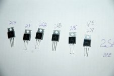
Thank you. I took off the 2SA968 last night and glad I did-one of them was a good one with a hFE reading of 317 while the other 3 gave readings 163, 175 and 183. I suspect and from my readings about counterfeit transsitors, that the lower hFEs are counterfeits. I went ahead and ordered the substitutes, 2SA1011/2SC2344, a few days ago. I just hope they are legit. Kaplaars, I tried to get your guy to send me an invoice for original replacements, no reply from him. What was really discerning about the 2SA I took off my boards, is that one of the 2sa was from a different batch (Y 050 with a K on top), the one that has a hFE reading of 183, and of the three others (9F1E with a T on top), one stood out with a reading of hFE 317; an outlier from the others who has readings 163 and 175. I did attempt to make a batch reading before soldering, but with only DMM hFE testing; maybe not a good way to get match transistors?David, these look like genuine Toshiba")
Attachments
David, 2sa968/2sc2238 have a hFE between 70 and 240 what depend of the fact are they O (70-140) or Y (120-240) range. So hFE 317 is definitively out of the hFE range.
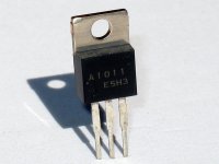
Don't mix, for example, 2sa1011 and 2sc2238 or 2sa968 and 2sc2344. Use only Sanyo's or Toshiba's.
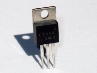
Here is the picture of the genuine Sanyo's so you can compare with those that you will get.
Don't mix, for example, 2sa1011 and 2sc2238 or 2sa968 and 2sc2344. Use only Sanyo's or Toshiba's.
Here is the picture of the genuine Sanyo's so you can compare with those that you will get.
Attachments
2sa968/2sc2238
I did not get my Sanyo's yet. I really want to go with Sanyo's since it seems that would make sense to install transistors that will be available in the future (or in the Present for that matter), But I would also, just for experiment and record, try good pair of Toshiba's. Can you tell me what possible cause for the hFE 317 difference. Since I didn't get this prior to soldering, could it have been cause by to high soldering temperature? Now I am worried about these transistors. Earlier we talked about members who dropped out because of the high cost of this and other projects and this project's cost is very high, I am upset that there could be bad sellers/transistors out there who/that could sabotage the expense/projects. Right now, I ordered smoothers, transfos and transistors to build a high voltage power supply from, a project from the book, 'High-Power Audio Amplifier Construction Manual' by G. Randy Slone. I attached an image of the schematic. Kaplaars, what do you think?David, 2sa968/2sc2238 have a hFE between 70 and 240 what depend of the fact are they O (70-140) or Y (120-240) range. So hFE 317 is definitively out of the hFE range.
Don't mix, for example, 2sa1011 and 2sc2238 or 2sa968 and 2sc2344. Use only Sanyo's or Toshiba's.
Here is the picture of the genuine Sanyo's so you can compare with those that you will get.
Attachments
Thanks Nico !
But if there is interest we can assist other prospective buyers and possibly get a better price?
Regards
Jozua
I would be in on a group buy of heatsinks. Good suggestion.
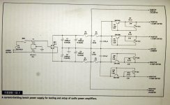
I did not get my Sanyo's yet. I really want to go with Sanyo's since it seems that would make sense to install transistors that will be available in the future (or in the Present for that matter), But I would also, just for experiment and record, try good pair of Toshiba's. Can you tell me what possible cause for the hFE 317 difference. Since I didn't get this prior to soldering, could it have been cause by to high soldering temperature? Now I am worried about these transistors. Earlier we talked about members who dropped out because of the high cost of this and other projects and this project's cost is very high, I am upset that there could be bad sellers/transistors out there who/that could sabotage the expense/projects. Right now, I ordered smoothers, transfos and transistors to build a high voltage power supply from, a project from the book, 'High-Power Audio Amplifier Construction Manual' by G. Randy Slone. I attached an image of the schematic. Kaplaars, what do you think?
David, this transistor, simply, is not genuine. Most likely not even 2sa968, but some generic type.
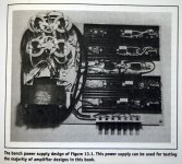
Bench PSU
I forgot to mention that the limiting supply output are for non-continuous use as the author warns that the series pass transistors will dissipate considerable heat if the current-limiting (1.5A) values are exceeded, so they should be adequately heatsinked. This Bench Power Supply was intended to be plugged into a variac so that the dual-output voltage levels are infinitely adjustable by the variac to the voltage of whatever transfo/secondaries setup you use. I plan on using a ~62V/8A transformer.
I forgot to mention that the limiting supply output are for non-continuous use as the author warns that the series pass transistors will dissipate considerable heat if the current-limiting (1.5A) values are exceeded, so they should be adequately heatsinked. This Bench Power Supply was intended to be plugged into a variac so that the dual-output voltage levels are infinitely adjustable by the variac to the voltage of whatever transfo/secondaries setup you use. I plan on using a ~62V/8A transformer.
Attachments
2SA968
Yes, sorry to beat a dead horse. Thanks. DavidDavid, this transistor, simply, is not genuine. Most likely not even 2sa968, but some generic type.
I forgot to mention that the limiting supply......
Hi Spurtle,
Randy had some very nice ideas and the test supply including a variac is one of them.
Keep in mind Randy did not intend this supply to be used for testing a 100 watt class A amp.
Unless you reduce the KSA100 bias to a few hundred mA just for testing purposes and once working increase the current, this power supply is a waste of money unless it is essentially for future projects.
A final comment though, there may not be much need for future projects since the KSA100 in not easily beaten.
Last edited:
Bench Power Supply
Now, this is what I like to hear, "....KSA100 not easily beaten!Hi Spurtle,
Randy had some very nice ideas and the test supply including a variac is one of them.
Keep in mind Randy did not intend this supply to be used for testing a 100 watt class A amp.
Unless you reduce the KSA100 bias to a few hundred mA just for testing purposes and once working increase the current, this power supply is a waste of money unless it is essentially for future projects.
A final comment though, there may not be much need for future projects since the KSA100 in not easily beaten.
Transistors
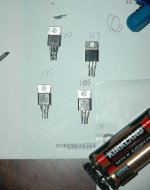
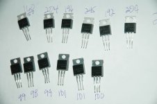
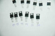
Well. Let's kick the horse to see if it is alive. My replacements and substitutes just came. I did a hFE evaluation and here are the results:Yes, sorry to beat a dead horse. Thanks. David
Attachments
Thanks Nico !
I phoned this afternoon but Ivan is only back next week ! But if there is interest we can assist other prospective buyers and possibly get a better price? I will definitely follow up next week.
I have been holding back with this project as I prefer the compactness of the tunnels despite the disadvantages of the long wires.
Of course on a big heatsink one could use flatpack transistors with shorter wires which I am told are much better.
Regards
Jozua
Jozua, If you guys can collaborate and design your specific chassis in high res CAD drawings, I have professional laser cutting and NC bending available to make the chassis parts for your exact needs and group buy.
hFE measuring
Is there a setup I can build?
Yes, I am afraid you got me there. I do not have a proper circuit setup to properly measuring hFEs. Many have said that they felt comfortable using transistors that were, at least, made from the same batch. But yes, being that I like to record measurements for future comparisons, it would be totally wise to properly setup devices before making such measurements.David is your hFE measurements the result of a multi meter, This normally is the small signal characteristic in other words IC of 1 -5mA was used. I would measure hFE in a circuit similar than that it is used in.
Is there a setup I can build?
Some, or maybe many, DMMs with an hFE function, test with a constant Ib.
The meter then reads the Ic, or could it be Ie, and this gives a direct reading of the hFE, for that (unknown) Ib.
Look at your results, varying from 98 to 204.
Do you know Ib, or Ic, or Vbe, or Vce or Tj or Pq?
That is the problem, or rather the series of problems. Neither you, nor the rest of us, know anything about the hFE values. They cannot be compared to any other folks' data.
Biggest problem is that the 204 devices is passing ~ twice the current of the 98 device and thus Pq is roughly double. This changes the Tj more and leads to a higher gain and thus a higher hFE reading.
You already have the multimeter. You only need a voltage supply and a few resistors to carry out a useful hFE measurement that can be approximately compared to other data and more particularly tested at the current and voltage that you intend using in circuit.
Jozua, If you guys can collaborate and design your specific chassis in high res CAD drawings, I have professional laser cutting and NC bending available to make the chassis parts for your exact needs and group buy.
Nico
Thanks for the offer. Kaplaars has fired up my interest in this project.
Your heatsinks are not the tunnels I am looking for. In fact I have quite a huge amount of them in stock but the mere physical size and weight will force me to build monoblocks ! However I might take you up on building a professional looking enclosure for me
This weekend I just got a hunch that the two 550000 uF caps per channel in my 50 watt Krell clone were a but 'slow'. Adding 10 000 uF (Rubycon) to each channel totally transformed the amp. Much more Krell sounding in terms of dynamics and slam. Possibly even better than my original KSA 50 Mk2! Only concern at this stage is that I somehow think the Krell 50.2 had more soundstage depth but that could just be a lack of burn in with the new caps.
It is now a case of replacing the Alcon caps with 10 000uF X4 Rubycons or using the Mundorf 47 000 powerlytics which I have been sparing for the Krell 100 clone?
I now realise one can 'tune' the sound by the choice of caps you use in the power supply.
Regards
Jozua
Last edited:
2SA1011/2SC2344
I got the Sanyo's a few day ago and I was in for a shock. I did not notice the order made were for T0-3 types. These were substitutes for 2sa1011/2sc2344 by mouserelecDavid, 2sa968/2sc2238 have a hFE between 70 and 240 what depend of the fact are they O (70-140) or Y (120-240) range. So hFE 317 is definitively out of the hFE range.
Don't mix, for example, 2sa1011 and 2sc2238 or 2sa968 and 2sc2344. Use only Sanyo's or Toshiba's.
Here is the picture of the genuine Sanyo's so you can compare with those that you will get.
Attachments
I don't understand. Didn't you got those from the first picture?
Well. Let's kick the horse to see if it is alive. My replacements and substitutes just came. I did a hFE evaluation and here are the results:
spend time checking and adjusting the local decoupling capacitors.............I now realise one can 'tune' the sound by the choice of caps you use in the power supply. ........
If the output is jumping around when transients appear then the amp can never sound right no matter what you do to the PSU. It after all is many tens of millimetres away from the output devices and drivers.
The Voltage amp stage is much closer and it will be affected by the internal supply rails jumping around as the outputs demand current and shut down again.
2sa968
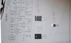
No, these are new ones from PacificSemi.com. They have 2sa968, but they sent substitutes, 2sa1302/2sc5200, for your 2sa1011/2sc2344 and I was taken aback by their physical size, T0-3P, compared to T0-220. The substitutes are 150watts with a base current of 2.0A at 200Volts. Much stronger, no?I don't understand. Didn't you got those from the first picture?
- Status
- This old topic is closed. If you want to reopen this topic, contact a moderator using the "Report Post" button.
- Home
- Amplifiers
- Solid State
- Stolen Trademark Amplifier from Jim's Audio on EBAY