Im probably not looking hard enough, but where on the PCB is the STK4050v? Besides all the capacitors and resistors on the board I only see the op-amps and some little motorola IC's.
mine is the PF15TL "plus", I dont think that would really make any difference though.
mine is the PF15TL "plus", I dont think that would really make any difference though.
duratothemax,
I am reasonably sure that Definitive Technology moved from those chip amps to designs without mains transformers.
ie be careful!
sp
I am reasonably sure that Definitive Technology moved from those chip amps to designs without mains transformers.
ie be careful!
sp
Yeah I definetly wont touch any of the capacitors or stuff like that. Hopefully the original poster will see this and maybe post some pics of the repair.
Only half of the resistors are labled it seems, Ill keep looking for R89
thanks
Ben
Only half of the resistors are labled it seems, Ill keep looking for R89
thanks
Ben
Mine is a PF15TL "plus" model. After going over the PCB schematics it seems there are quite a few differences... 🙁 😕
Ben
Ben
They should definitely not look like that and need to be replaced. Before that you should try to determine, why they look like that. Maybe U3 has to be replaced. And right below Q4 (on the right side in the photo) there is another resistor that looks overheated.duratothemax said:I dont know if those two resistors are supposed to be that color, they look a little brown???
The labels are below the resistors. You will have to lift them out to read their labels.duratothemax said:Only half of the resistors are labled it seems
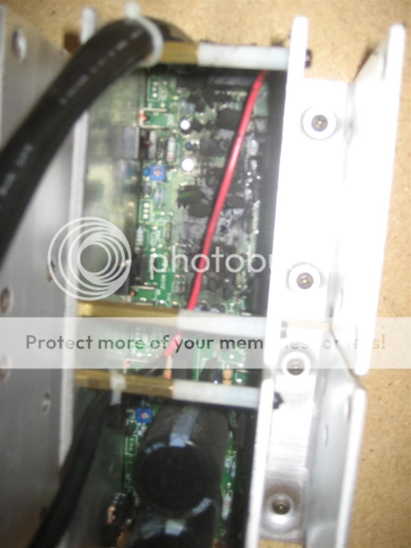
Should be screwed or clamped to the heatsink.duratothemax said:but where on the PCB is the STK4050v?
duratothemax, there must be an amplifier section that either uses an IC Power Amp (that is STK series or equivalent) or Mosfets to drive the subwoofer. The pictures are only showing the pre-amplifier section with multi-stage op amps (IC's). This PCB is probably the preamp section, try and look for another PCB that will have the amplifier section... the IC or the transistor is attached to the heat sink to dissipate heat. There you will find the R89 resistor. By the way, it is 19.1 kohms and not 19.5. Do not attempt to change it to 20 kohms because I think the design was for it to give way (you know, like a fuse?) is the sub is played to point of clipping. All the best.
Duratothemax, with respect to post of Pacificblue, Q4 (transistor) is involved with power supply- the fact that your unit powers up only tells you that this component is not defective. U3 (the IC close to the suspicious looking resistors) is responsible for turning the red power light on when the unit detect a signal from the inputs. Again, since you unit turns on when it detects a signal this tells you this is not at fault. I still believe the previous post that the culprit is R89- it is connect to pin 4 of the STK4050v and to the mute of U3- with this info alone, you know it is involved with sound production because when it opens, it will mute the system. Happy fixing. Hope this helps.
Thats great thanks for the help everyone! Yes the output stage is separate on the PF15TL "plus", wheras I think on the non-plus model its all integrated into one module that has the heat sinks sticking out the back of the sub box itself.
the "plus" model is supposedly 500w RMS. Its actually inside the box, I think ill have to take the driver out to get the heatsinks and stuff out to diagnose it. Being double the rated wattage Would it use a different power amp circuit than the STK4050V? Would my "Plus" model use the same 66v rails and power supply as the non-plus model? Ill pull it out and take some pictures.
I see now the resistor labels are underneath the resistors themselves, I feel pretty stupid for not realizing that!
thanks
Ben
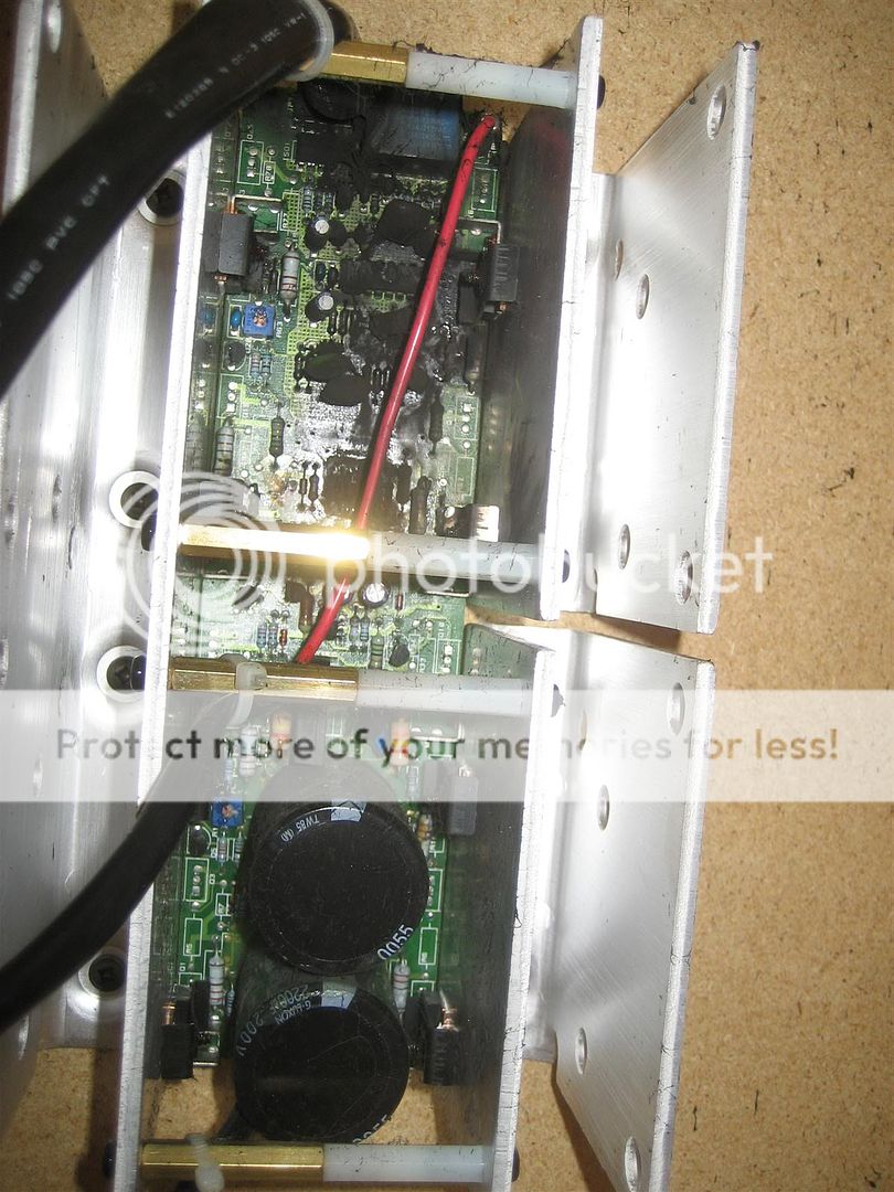
If it uses two 10,000 mFd 80 volts capacitors, its voltage is playing around 66 to max of 70 volts. Company won't be using 80 volts caps and load it a 75 volts...that's a meager 5 volts + or - fluctuation...the caps might burst (although not usually). Please be very careful not touching the contacts of the caps unless you discharge them... it's quite a painful jolt...may disrupt your pacemaker if you have one. As I learned from the experts posting here in diyaudio, the 500 RMS of the PF15TL + can be achieved by increasing power supply, so probably the limiter IC was adjusted or the power supply itself was changed. But this is a guess, the STK4050v will probably be still used in your amp. Happy fixing. Will await your pictures. By the way, the amps of the Definitive Tech PF15TL and the PF15TL + are probably one of the best sounding amp for a subwoofer I've heard...for the price it sells. They are better than the latest Supercube amps (which are even rated at 600 to 1000 watts but use a 32 ohm driver!).
Ok so I heard back from Definitive. They were a huge help and gave me the schematics no questions asked. Downside is the replacment amp is like 350 bucks.  😱
😱
thats more than I paid for it, so Ill try to diagnose it myself.
the schematics look different from the PF15TL non-plus, maybe someone can make sense of them?
thanks
Ben
😱 thats more than I paid for it, so Ill try to diagnose it myself.
the schematics look different from the PF15TL non-plus, maybe someone can make sense of them?
thanks
Ben
Attachments
Duratothemax, my apologies to you but the sound stage of your sub amp is definitely different from the PF15TL. No it doesn't use the STK4050v but uses pairs of MOSFETS. Thanks for sharing the schematics- this is actually the same amp they use for their newer SUPERCUBE III, rated at 700 watts but uses a 36 ohm driver. Again, sorry, can't help you with this one. Surely, someone out there is more knowledgable and will probably give a helping hand. Or you can purchase a replacement amp from Def Tech... might turn out to be more frugal.
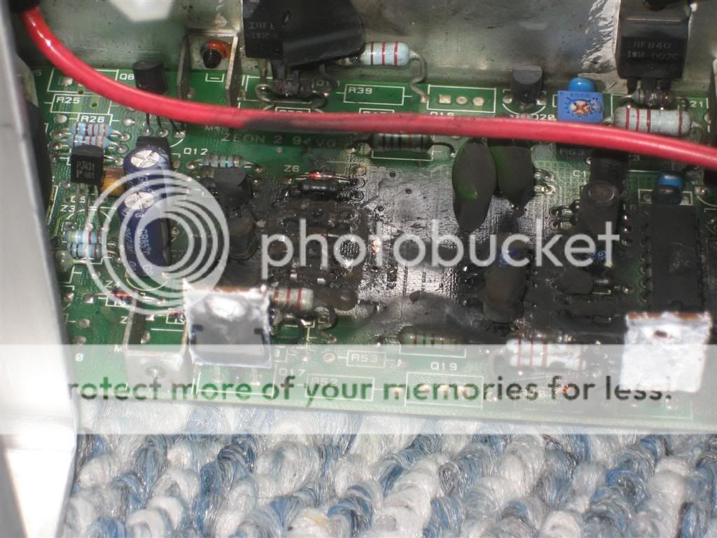
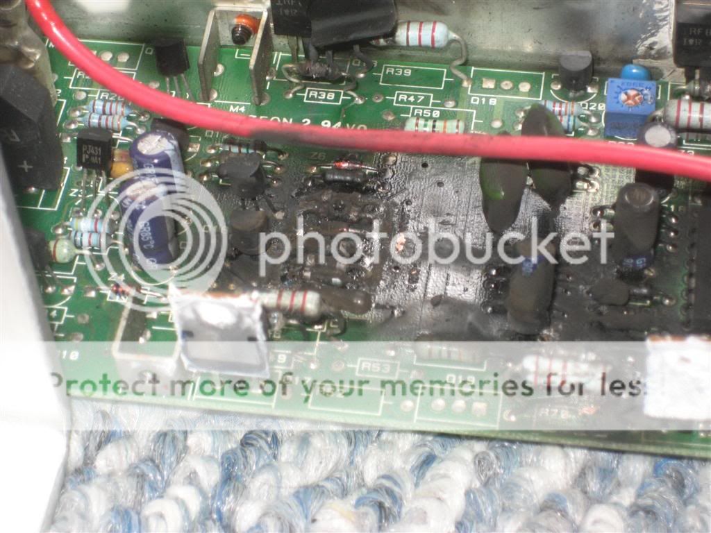
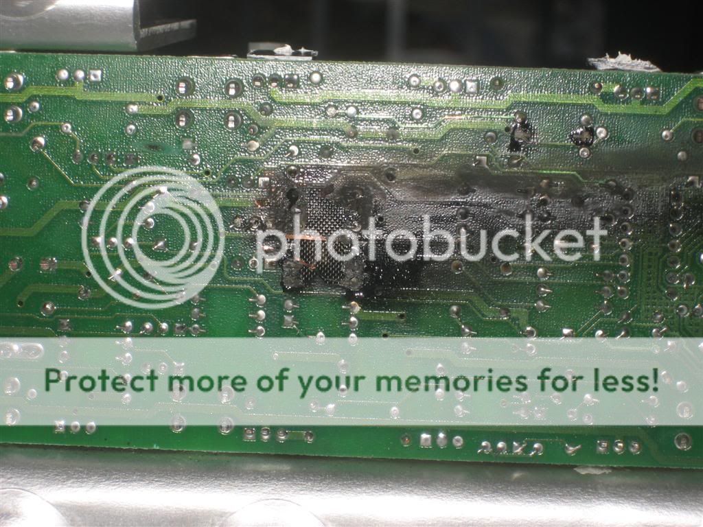
well looks like Im screwed... took apart the 'real' part of the amp and found this. Surprised the darn thing didnt catch on fire.
I will pull it out tonight and clean it off to try to figure out where the problem started and maybe with ANY luck at all I can replace that one component and be good to go again. No simple resistor will fix this one. 🙁
If anyone feels like tackling this, Ill gladly pay them to fix it!!!
thanks
Ben
I will pull it out tonight and clean it off to try to figure out where the problem started and maybe with ANY luck at all I can replace that one component and be good to go again. No simple resistor will fix this one. 🙁
If anyone feels like tackling this, Ill gladly pay them to fix it!!!
thanks
Ben
Duratothemax, I suggest you write to Stuart Easson, one member who posted a reply in this thread. He can help you. Or you can buy a good amplifier from Rhythmikaudio.com but you might have trouble with your driver...remember this is 36 ohms.
It says 75 ohms on a sticker on the voice coil tho??? 😕
I talked to Definitive, they said they can replace just the high level output stage board (im assuming the input stage and low level processing board is still good because the amp clicks on and the LED lights up as normal) for 175$ with a one year warranty. Its a fair chunk of change, but not really THAT unreasonable in my opinion, especially with the 1 year warranty.
Ben
u are absolutely correct. yes your preamp may still be functional but just be careful when you put in the replacement output stage from Def Tech bec you haven't really determined the reason why your output got fried. check to see if there are any wires that may have caused a short circuit specially in the speaker (driver) area. $175.00 is still a lot of money!
Is there ANY possibility that a problem with the input stage can fry something in the output stage? I mean I know anything is possible, but I would think the probability would be low...
From looking at the schematics it looks like everything is centered around the positive and negative output stages, moreso on the negative output stage.
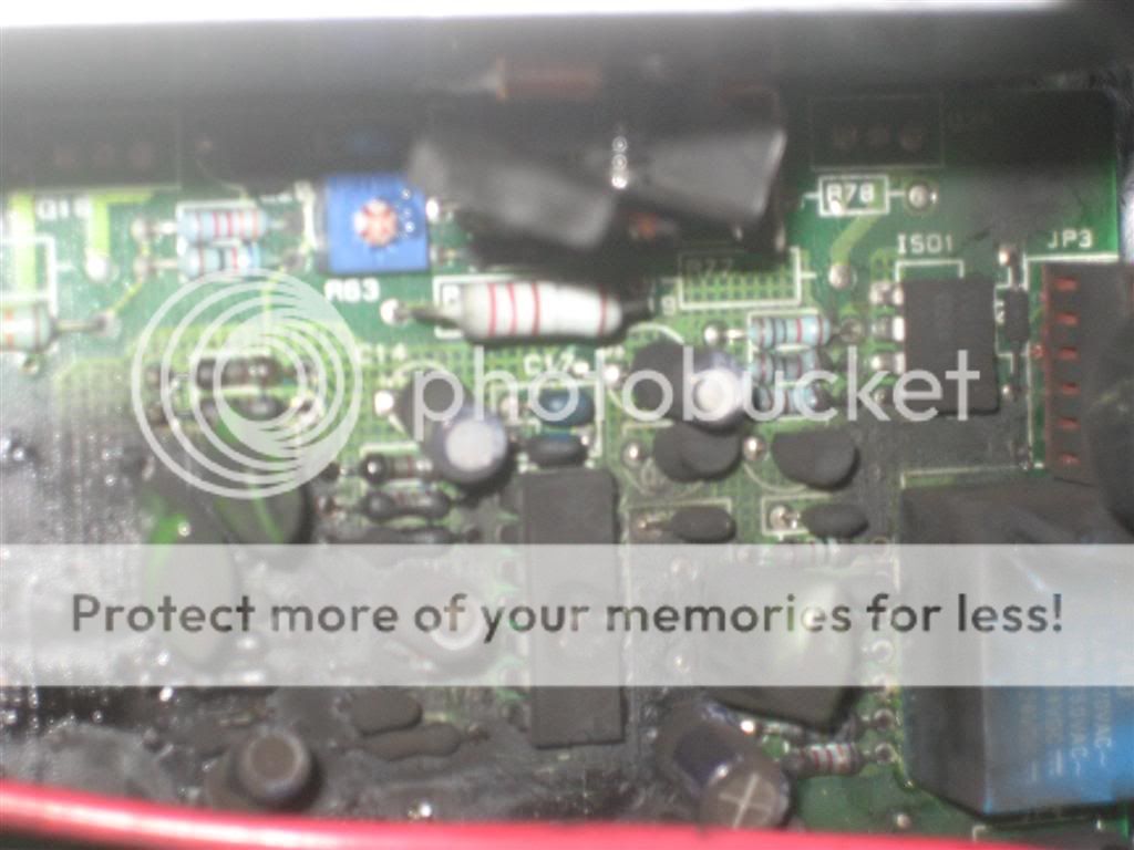
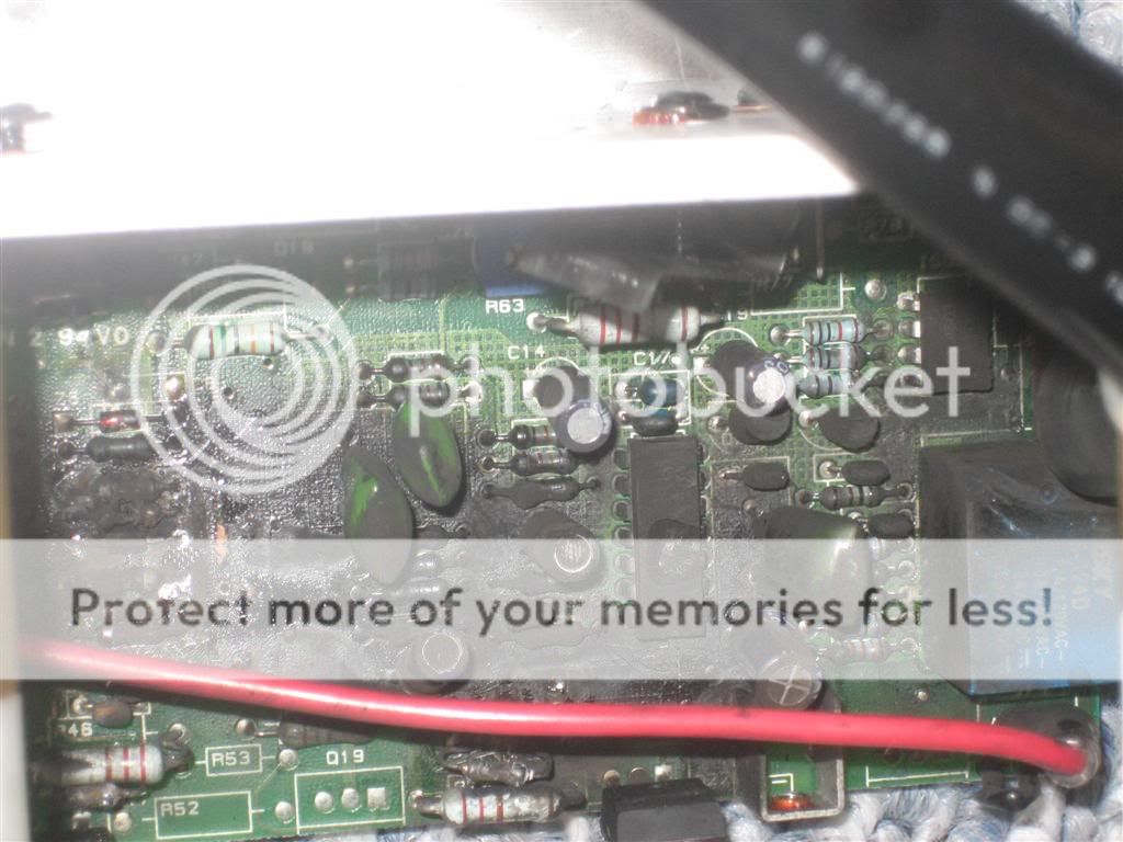
Most everything is so burned I cant even see the markings and designations on the PCB, but the destroyed components I can tell are:
the "U1" LM324 op amp has a huge section blown out of the center
Id say half of the resistors are blown/melted
blown resistors:
R38
R39
R49
R46
R4
R70
R16
R37
R38
R36
R72
R2
blown transistors:
O18
O19
Blown IC's
U1 (LM324)
ISO1
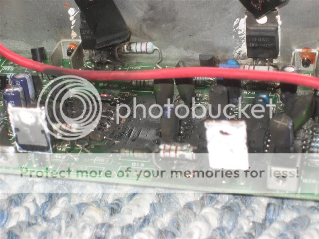
I think 4 of the 6 FETs might be blown too, but Im not sure.
Massive catastrophic failure for sure, there is no fixing this. There are some good holes blown right through the board. 🙁
thanks again for all the advice!
Ben
From looking at the schematics it looks like everything is centered around the positive and negative output stages, moreso on the negative output stage.
Most everything is so burned I cant even see the markings and designations on the PCB, but the destroyed components I can tell are:
the "U1" LM324 op amp has a huge section blown out of the center
Id say half of the resistors are blown/melted
blown resistors:
R38
R39
R49
R46
R4
R70
R16
R37
R38
R36
R72
R2
blown transistors:
O18
O19
Blown IC's
U1 (LM324)
ISO1
I think 4 of the 6 FETs might be blown too, but Im not sure.
Massive catastrophic failure for sure, there is no fixing this. There are some good holes blown right through the board. 🙁
thanks again for all the advice!
Ben
OK I feel totally stupid I didnt notice this before...but am I understanding the schematic correctly in that the input stage basically does all the processing, then encodes it into a PWM signal, sends it to the output stage/amp and the amp decodes the PWM and then obviously amplifies it.
Seems kind of odd and a lot of extra circuitry, expense, and work for nothing...whats the point? Because the high voltage might induce some noise if it was transferred as an analog low level signal????
so U3 on the input/processing board looks like its what generates the PWM signal and, so hopefully the output stage going nuclear didnt backfeed a voltage spike across the PWM data signal line and break something in the input board/processor.....
Or maybe im all wrong??? 😕
Ben
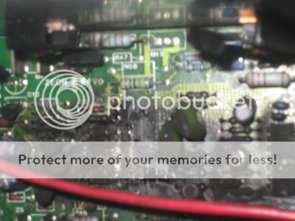
This damage can be due to shorted wires goin to your driver (speaker). It is so badly damaged even the board might not be salvageable! You must remember the parts you listed are the obviously and grossly burned ones but the other resistors and capacitors which look ok may not be ok. It will be best and frugal that you get the amp being offered to you by Definitive Tech. I do not believe your preamp or the low level part where the inputs and volume control is is at fault. This burned amp can only result from a short circuit. Please check that your driver is not burned too. If you so decide to fix this, you can go to Mouserelectronics.com for parts.
Sorry for resurecting this thread once again, but I am looking at converting the PF-15TL to a sealed box arrangement (less boomy)and I want to extend the low frequency response of the internal amplifier.
As an electronics layman, I measured the voltage output of the amp with a constant voltage input of varying frequency (10 to 100 hz) to the low level inputs. There seems to be quite a drop off from the amp below ~35Hz.
Any easy way for flat amplifier response down to ~10Hz or so?
I see there is a bandpass filter which can be part of the problem, but I'm really not sure this is what I should attack. The low frequency fall off is really steep. Any help would be appreciated.
Attached is the schematic.
http://www.diyaudio.com/forums/attachment.php?s=&postid=1157099&stamp=1173815791
- Status
- Not open for further replies.
- Home
- Amplifiers
- Chip Amps
- STK4050V and it's use in Definitive Tech PF15TL subwoofer