I have two STK 4191ii amps and thier THD is typically 0.4%. I have managed to find couple of pin compatible STK 4191v which has THD of 0.08%.
The STK 4191ii circuit has out with only snubber [4.7R + 0.1Uf].
Although pin compatible 4191V circuit has 3 MicroH coil parralel with 4.7R in addition to the snubber. Data sheet says it is to block ocsillation.
My PCR does not have room for new coil and R!!! Are they essential?
Can i omit them?
If not how can I wind a 3 microH coil? Please advice me!
Thanks in advance!
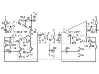
4191ii schematic
The STK 4191ii circuit has out with only snubber [4.7R + 0.1Uf].
Although pin compatible 4191V circuit has 3 MicroH coil parralel with 4.7R in addition to the snubber. Data sheet says it is to block ocsillation.
My PCR does not have room for new coil and R!!! Are they essential?
Can i omit them?
If not how can I wind a 3 microH coil? Please advice me!
Thanks in advance!
4191ii schematic
Attachments
Do you have any enameled wire? Look at another amp and do something similar. I don't think the value is very critical.
A 20 GA should do it, 18 GA would be okay too. Solder one end to the resistor and wind the wire so each turn touches the previous one. Solder the other end.
-Chris
Edit: the added resistor should be about 2 watts.
A 20 GA should do it, 18 GA would be okay too. Solder one end to the resistor and wind the wire so each turn touches the previous one. Solder the other end.
-Chris
Edit: the added resistor should be about 2 watts.
Hi Chris
I have 18 enameled wire. So if I wind the wire ariound the resistor without giving much notice to the value is it OK?
This inductance calculator gives mere 3cm long coil with the diameter of 1cm using 18 gauge wire for the amount of inductance! With some 28 turns!http://www.oz.net/~coilgun/mark2/inductorsim.htm
I thought of adding the coil outside the resistor parralel to R. Is it OK to wind the coil around the R?
Thanks
Further within the size allowed by the resistor I can get more inductance if I use smaller GA wire like 24 or 28 Ga which I have.
Please tell me whether the winding around the R is OK than putting air core coils! I have not seen this LC topology in the amps I examined as I am a newbee!
TKS
Please tell me whether the winding around the R is OK than putting air core coils! I have not seen this LC topology in the amps I examined as I am a newbee!
TKS
Winding 20GA around the resistor with specified inductance of 3 µH gives a fairly large coil. So i decided to wind only once around the resistor with negligible inductance when checked with the meter. Is this the correct method? I need to be 100% sure as messing around STK modules can give my speakers untimely death!
Please help me any other experts on the subject!
Please help me any other experts on the subject!
Hi kaushama,
Give it a try and see if it oscillates. Watch the current draw (dead giveaway). An oscilloscope is the better tool.
You may find you need 2 or three layers. The point is, you need to use what is required to kill oscillation. There is no other choice on that.
-Chris
Give it a try and see if it oscillates. Watch the current draw (dead giveaway). An oscilloscope is the better tool.
You may find you need 2 or three layers. The point is, you need to use what is required to kill oscillation. There is no other choice on that.
-Chris
Hello
Regarding the inductor you asked for "3uH"")
Forget about it "Winding the coil on resistor" is NOT a good idea in deed, I will tell you exactly how to wind yours !!
Inductance = 3 uH
Wire Diameter = 1 mm
Coil Length = 25 mm
Coil Diameter = 15 mm
DC Resistance = 0.0227 Ohm
Length of required wire = 1.04 m
Number of turns = 20
"mm" stands for millimeter, and "m" stands for meter.
This is a single layer air-cored coil, the coil length and diameter are somewhat large, but that was to obtain a single layer coil in deed, thats why I told you not to wind it on a resistor because its air-cored one, as you can NOT predict the final inductance of the coil when you wind it on a resistor. Not forgetting the physics thingy, electrons in the resistor will be disturbed by the magnetic field created by the coil, I don't know what the final effect will be.
BTW, I have not used any coils at the output of the STK4191V veroboard prototype and did not have any oacillations problems when I made tests using an oscilloscope, I posted the PCB designs of STK4191V where output coils are included as I remember, muting, and protection some where on the forum, they are really useful in deed, if any one needs the eagle files, let me know.
MetaL.
Regarding the inductor you asked for "3uH"
Forget about it "Winding the coil on resistor" is NOT a good idea in deed, I will tell you exactly how to wind yours !!
Inductance = 3 uH
Wire Diameter = 1 mm
Coil Length = 25 mm
Coil Diameter = 15 mm
DC Resistance = 0.0227 Ohm
Length of required wire = 1.04 m
Number of turns = 20
"mm" stands for millimeter, and "m" stands for meter.
This is a single layer air-cored coil, the coil length and diameter are somewhat large, but that was to obtain a single layer coil in deed, thats why I told you not to wind it on a resistor because its air-cored one, as you can NOT predict the final inductance of the coil when you wind it on a resistor. Not forgetting the physics thingy, electrons in the resistor will be disturbed by the magnetic field created by the coil, I don't know what the final effect will be.
BTW, I have not used any coils at the output of the STK4191V veroboard prototype and did not have any oacillations problems when I made tests using an oscilloscope, I posted the PCB designs of STK4191V where output coils are included as I remember, muting, and protection some where on the forum, they are really useful in deed, if any one needs the eagle files, let me know.
MetaL.
Hi metal,
Winding the output choke on the resistor is common pratice in the audio industry, and has been for over twenty years. If the inductance does vary, it will increase. Not a terrible thing. The value is not critical.
As for the need to have an output choke, if the designer of the chip says you need it, you need it. This is to make it stable with most common loads and cables. If yours didn't happen to oscillate - great! But that is hardly proof you don't need the choke. I've seen more than my share of marginally stable amplifiers out there, don't add to them.
Hi kaushama,
More inductance is not better. You just need some minimum value to keep the amp from becoming unstable with a load. Dual and triple layer coils are fine, normally I see a dual layer or single layer.
-Chris
anatech said:Hi metal,
Winding the output choke on the resistor is common pratice in the audio industry, and has been for over twenty years. If the inductance does vary, it will increase. Not a terrible thing. The value is not critical.
As for the need to have an output choke, if the designer of the chip says you need it, you need it. This is to make it stable with most common loads and cables. If yours didn't happen to oscillate - great! But that is hardly proof you don't need the choke. I've seen more than my share of marginally stable amplifiers out there, don't add to them.
-Chris
Hi anatech
I won't say you don't need the coil at the output when the manufacturer says its a must, but my prototype didn't oscillate and that was great for me in deed, thats what I wanted to say. I am sorry if I mislead some of the invaluable members and they thought the coil isn't necessary.
Originally posted by anatech
A common practice
So what, some manufacturers used to put the capacitor inside the inductor when manufacturing crossovers, and some used to put the PSU main smoothing capacitor inside the toroidal transformer and all were a common practice !! I saw that my self, and that was to save space, unfortunately I don't remember what brand. If you read what douglas self said about it, you will be really amazed, as happened to me at the first glance. The magnetic field of inductor did affect the capacitor value afterall, and that was bad and yielded the change of calculated/expected crossover frequency at least.
The same applies to a resistor, as electrons inside a resistor will be surely affected by a magnetic field, and you can't expect how the resistor will behave, I don't think that providing space for a 25 X 15 mm coil on the PCB shall introduce problems to any of us.
For Nordic...
Inductance = 0.7 uH
Wire Diameter = 1 mm
Coil Length = 15 mm
Coil Diameter = 10 mm
DC Resistance = 0.0087 Ohm
Length of required wire = 39.6 cm
Number of turns = 11.4
PS
I don't know if there is a preferred ratio between coil length & hight, so, if any one got any comment about that, please let me know.
MetaL
- Status
- This old topic is closed. If you want to reopen this topic, contact a moderator using the "Report Post" button.
- Home
- Amplifiers
- Chip Amps
- STK 4191v question