Success! SPP17N80C3 installed with a slightly larger heat sink that I found in my pile of parts. The larger heat sink is possibly not necessary, but why not? The tubes are now biased to about 45 mA, and the amplifier works as it should. I can't hear any hum at all with my ear to the speaker. Significantly more silent now compared to when the choke was connected.

@zintolo Your questions are really interesting, but I'm afraid they are beyond my level of expertise... I just blindly followed the BH and DCPP designs with some input from Merlin's HiFi and Power Supplies book. If I had the time I'd be keen to experiment on some of the aspects you mention.Hi, as you are working on this design, I ask you some details I came to over the years.
Do you feel it is needed to have cascoded CCS on phase inverter tail and power drive loads, or simple ones with a zener (to raise the sensing resistor) is enough?
My experience is that it is not needed.
Is it needed to have separate reference voltage for the base of the CCS, or one single is enough as far as negative voltage is low enough not to be overloaded during peaks?
In my experience it is enough to have one reference voltage for all three CCS.
Do you set powerdrive current to fit how many times the minimum requirement for slew-rate?
I use low UL values (around 20%), so input capacitance of the output tubes is low (pentodeish), but still I stay at 5 to 10 times the needed current.
How do you decide the V+ and V- for the powerdrive?
If I stay in AB1 I stay usually at +30 and 3 times the negative biasing voltage. This, together with the above current, usually set the mosfets well below 1 W, so no need to heatsink.
I’ve had an epiphany last week, using higher (43%) UL to triodize the output tubes, then apply positive Shade feedback to have horizontal loadline for the phase splitter, reducing his distortion, then apply an active global negative feedback to recover the damping factor.
Without that global negative feedback I got 0,03% THD at 1 Wrms and 1% THD at 40 Wrms, in both cases is maiy 3rd harmonic, all the others are at least 20 dB below. Applying the active global feedback I should get around 100 times less distortion and a DF around 15.
Great to hear another build on the way. Make sure you use a 2W resistor for R208 in the ripple filter as detailed in the above posts.I starting soldering components on the PCB. I noticed in the BOM there are 3 values for resistors R323 and R423. I installed the middle value 33K but I am not sure if this is correct.
@gingertube gave a recommendation for the value of R323/423 somewhere (either this thread or the main thread, can’t remember). 22k was what I went with based on that - I didn’t experiment, however. If you stick with 33k let me know what you think.
@tristanc,
I want to thank you for your excellent support of this project. I followed closely this thread and I replaced
I plan to use Toroidy power and output transformers as @tbaashus used. His amp looks great. I will use the same chassis he used too.
Not sure about the advantages of a toroid output transformer versus regular one though.
I want to thank you for your excellent support of this project. I followed closely this thread and I replaced
- Replace R208 and R209 with 2 W resistors
- Replace R206 and R207 with 1K resistors
I plan to use Toroidy power and output transformers as @tbaashus used. His amp looks great. I will use the same chassis he used too.
Not sure about the advantages of a toroid output transformer versus regular one though.
I actually put the 100R (R206 and R207) resistors back, just to see if it caused problems with the replacement transistor. The amplifier has been in use every day for a week now with SPP17N80C3 installed. I'm a bit anxious every time I turn it on though, half expecting either no sound at all or a load hum ... But that will pass. I'm very happy with the amplifier.Replace R206 and R207 with 1K resistors
I also installed SPP17N80C3 as a replacement for the obsolete MOSFET.
About Toroidy output transformers vs regular ones. I don't know if there are any advantages, but I can't complain about how the amplifier sounds. And the Toroidy transformers do look great in stainless steel.
@tristanc I remember @gingertube used 22k with KT77, not EL34.
IIRC I went to 39k with 460V B+, 23% UL and 270k instead of 220k on LTP plates, choosing the LTP CCS to get around half B+ on LTP plates. That, again IIRC, gave me a DF around 3.5.
IIRC I went to 39k with 460V B+, 23% UL and 270k instead of 220k on LTP plates, choosing the LTP CCS to get around half B+ on LTP plates. That, again IIRC, gave me a DF around 3.5.
yes, those Toroidy transformers look great with the stainless steel. Why didnt you use the same for the power transformer, i guess maybe it doesnt fit on the top.I actually put the 100R (R206 and R207) resistors back, just to see if it caused problems with the replacement transistor. The amplifier has been in use every day for a week now with SPP17N80C3 installed. I'm a bit anxious every time I turn it on though, half expecting either no sound at all or a load hum ... But that will pass. I'm very happy with the amplifier.
About Toroidy output transformers vs regular ones. I don't know if there are any advantages, but I can't complain about how the amplifier sounds. And the Toroidy transformers do look great in stainless steel.
It might be possible to squeeze in the power transformer on the top if the output transformers are moved to the sides. But there is plenty of space inside the chassis, so I figured it was a good place for it.yes, those Toroidy transformers look great with the stainless steel. Why didnt you use the same for the power transformer, i guess maybe it doesnt fit on the top.
https://www.diyaudio.com/community/threads/el34-baby-huey-amplifier.326920/post-6556084@tristanc I remember @gingertube used 22k with KT77, not EL34.
18k with KT77, never built with EL34 AFAIK.
I got my PCB and components, I upgraded the PCB to 2mm thickness since the board is so large. Got the the same chassis as @tbaashus, waiting for the transformers from Toroidy, again same as @tbaashus. I replaced the obsolete MOSFET with the last recommendation and also changed the resistors to the last recommendations. Thank you for sharing the information of those components, it saved me quite some time and agony.
The components are all installed on the board, I think I installed everything correctly, not absolutely sure about Q305, Q308 and Q405, Q408. I attached the pictures of my board, if anybody sees a mistake please let me know
@tristanc thank you for your awesome support for this project.
The components are all installed on the board, I think I installed everything correctly, not absolutely sure about Q305, Q308 and Q405, Q408. I attached the pictures of my board, if anybody sees a mistake please let me know
@tristanc thank you for your awesome support for this project.
Attachments
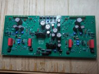
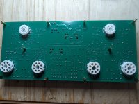
I think I installed everything correctly, not absolutely sure about Q305, Q308 and Q405, Q408
Looking good. Check the orientation of Qx05 and Qx08 against this photo. I think you’re good.
I’ll take a better look tonight.
You should remove R302 and R402, since you have installed RV301 and RV401. When you have removed the resistors you can set RV301/RV401 to 680R as an initial value.if anybody sees a mistake please let me know
Hello everyone,
I was lucky and got "Engineer's Baby Huey" PCB as a gift from my friend. So, sooner or later I will start soldering the board") But before starting, I would like to ask whether it is worth making at least a few improvements. First of all, the Ripple filter, perhaps the Jan Didden T-reg HV regulator would be worth paying attention to:
But before starting, I would like to ask whether it is worth making at least a few improvements. First of all, the Ripple filter, perhaps the Jan Didden T-reg HV regulator would be worth paying attention to:
https://linearaudio.net/t-reg-hv-regulator
https://www.diyaudio.com/community/threads/group-buy-for-jans-high-voltage-regulator.344165/
Second, heaters power supply. To change from AC to DC. To make linear DC regulator probably a little bit problematic because of high currents but maybe SMPS type will work? And third, change EL34 to KT77. Is it worth it?
Thanks in advance for any comments.
I was lucky and got "Engineer's Baby Huey" PCB as a gift from my friend. So, sooner or later I will start soldering the board
But before starting, I would like to ask whether it is worth making at least a few improvements. First of all, the Ripple filter, perhaps the Jan Didden T-reg HV regulator would be worth paying attention to:https://linearaudio.net/t-reg-hv-regulator
https://www.diyaudio.com/community/threads/group-buy-for-jans-high-voltage-regulator.344165/
Second, heaters power supply. To change from AC to DC. To make linear DC regulator probably a little bit problematic because of high currents but maybe SMPS type will work? And third, change EL34 to KT77. Is it worth it?
Thanks in advance for any comments.
- Home
- Amplifiers
- Tubes / Valves
- Stereo EL34 Baby Huey Build Log - an "Engineer's Baby Huey"