J_Hart_14 said:Problems today again...
I'd recommend investing in Morgan Jones "Valve Amplifiers" 3rd edition - this will give you some solid basis for designing an amplifier that works properly.
The current phase splitting and front end amplifier design has a severe ac imbalance by virtue of the configuration of the first stage. Sort of a broken Williamson if you will. (Look for information on this topology as well.) The first stage needs to have symmetrical resistance values in the plate and cathode circuit (no cathode bypass cap either.) as this the actual phase splitter in the topology you have chosen.
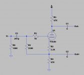
I've included a simple fix to your issue, it's off the cuff.. Note that it has 6dB of gain by virtue of the phase splitting it is doing, however to each output gain is unity. The resistor values are somewhat arbitrary, but should be close enough for the experiment or you can simulate to get better values. You can also remove the cathode bypass cap in your second stage which should improve overall balance slightly. Note you may need to tweak the value of R3 to get equal dc voltage drops across the 47K resistors. (About half the voltage should be across the tube and 1/4 across each of the 47K resistors for maximum headroom. For example Assuming 200V supply this means 50V across each resistor and 100V across the tube at a little over 1mA which is probably far from optimum for a 12AT7A. Scale R3, R4, R5 values down for higher plate current if desired.)
Attachments
What you are suggesting is that with just the phase inversion stage there is enough gain involved not to constitute adding another gain stage before the inverting stage. Back in my original design i do not see many differences between what you have just shown and what I had originally. With what you suggest it would easily drive the el34 in pentode mode, but If I change to the triode mode what amount of signal would be required to drive it to full capacity?
J_Hart_14 said:What you are suggesting is that with just the phase inversion stage there is enough gain involved not to constitute adding another gain stage before the inverting stage. Back in my original design i do not see many differences between what you have just shown and what I had originally. With what you suggest it would easily drive the el34 in pentode mode, but If I change to the triode mode what amount of signal would be required to drive it to full capacity?
The major difference is the drive to the next stage is symmetrical, currently you are driving one half of the 12AT7 driving the output tubes. If you are not planning on using feedback just this revision to the first stage ought to be enough otherwise use the other half of the 12AT7A for gain and direct couple it to the stage I previously posted. Take a look at the Williamson topology to see what I meant. Be aware that the Williamson may not be the best choice for you due to potential LF stability issues if the interstage resistor & coupling cap time constants are incorrectly chosen. (Can't post in more detail right now.)
Some of the other suggestions might be better choices as well, specifically the Mullard 5-20 topology which you can adapt to the 12AT7A quite easily.
To get more practical hints try brousing at www.triodeelectronics.com and scroll down to online schematics. Duncanamps does the same. Overview at phasesplitter configs with Arcosound; Genelec amps esp 30W and hosts of others and Harmon etc....the Mullard 20W LTP design is part of the standard workshop furniture.
richj
richj
- Status
- This old topic is closed. If you want to reopen this topic, contact a moderator using the "Report Post" button.