Hi
Thanks.I have something like 20 of those toroinds and I dont have any info for them, just dimensions. You should use pigh power material like coolMu. I doesn't have to have low permiabilty, but its good if it has high B(flux).
On ClassD page at the bottom ther are two links, wich both are for that amp. They are links to theads on this forum. There you will find schematics for amp, and read whole thread, because there are some mistakes on schemas.
I hope I will be able to hear my amp in car in few day, can't wait
Hi Luka et all.,
Ok ok. I know about saturation flux density and initial permiability. I have magnetics' ZP44413(also ZP44925) toroid for SMPS of this amp.
I know the mentioned threads but now, I understood the delay. 2113 or 2110 has shmit inputs therefore the resistors+reverse signaldiode and a cap will provide delay time. Also reverse diode ensuring fast fall time while the cap ensures lower rise time. The shmit input of 2110 corrects the inputs and finnally one can get a dead time on outputs. But, I am using an XOR CD4070 and it has propagation delay from input to output nearly >~100ns. Is this dead time not enough? And also in somewhere I saw 4069 inverters connected to achieve some dead time. 4070 or 4077 (XNOR) does nearly same thing with 4069.
Here are the data sheets :
http://www.ee.washington.edu/stores/DataSheets/cd4000/cd4070.pdf
http://www.ee.washington.edu/stores/DataSheets/cd4000/cd4069.pdf
And here is the data sheet of HIP 2100 ( my final chip for single ended module has 8ns delay maching and has internal boostrap diode)
http://www.intersil.com/data/fn/fn4022.pdf
Please have a look the data sheets and tell your ideas, may help me + any others who will DIY a class-D amp.
Regards
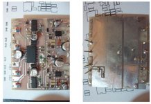
Here is the un finished PCB component Locations
Hi to every body, Now both channels of my HIP4081 stereo class-D amp works. I am desining the smd daughter borads with different ICs. One with smd HIP4081, other one with smd HIP2100 or ISL2111(3/4A drive capability) and the last one reðresented on the below in the enclosed file with IR2113(DIP). Main board will be flexible for application of all the daughter boards.
Hi to every body, Now both channels of my HIP4081 stereo class-D amp works. I am desining the smd daughter borads with different ICs. One with smd HIP4081, other one with smd HIP2100 or ISL2111(3/4A drive capability) and the last one reðresented on the below in the enclosed file with IR2113(DIP). Main board will be flexible for application of all the daughter boards.
Attachments
Forgot to say
Please excuse me, The unused output pins of CD4070 will be removed while inserting the chip into PCB. Otherwise the outputs will damage the chip internally or may cause much power dissapation than expected.
Regards.
Ps: please excuse me for "reðresented" . The reason of this mistyping my bad keyboard and I would like to type "represented"
well i'm trying to create a thread looking for 25wpc & 50wpc 12v modules and have had no luck searching for them here. i don't really understand all of these technical discussions. i'm not an electronics DIYer. i'm just looking to amplify a bicycle.
despite wasting my entire library hour registering here and searching class-D to no avail, this dang forum won't let me create a thread to find the mid power modules i couldn't find online except in products lists (not purchasable)
does anyone know where i can get modules with more oomph than my sonic impact class T and with less power draw than the 100W+ modules everyone here seems to be using?
can anyone tell my why this darn forum keeps ignoring my wasted attempts to find modules other than what everyone else is discussing (at least in their post topics) module "XJ-572-QR"
means nothing to me, but 25wpc & 50w monoblock does.
i'm a layman, not a techie. i can understand what a capacitor etc. is on a schematic, but have no idea how any of it works.
Hi Luka,
I could not fully test it yet. Because I was away for weekend. But, I tested both channels with my old test board 'shown in this thread' and can say only both are working without heat on mosfets for quiscent current for an hour. I did not give audio signal because, I do not have scope yet. But I really know, from the experiences i did on dip package, the sound is good. Also a point to imply, I realised when I finished the smd board; one can do the auxilary power supplies on the empty side of daughter board. So, one can put only +/- power supplies line plus GND and audio signal and mosfet outputs to the daughter board. Any way it is working, I will desing the main board for 4 channell. I will put here the scop results when i measured. Also will desing another daughter board with HIP4080 for the fifth channel. Hýýmm, output filters; T68-2(Micrometals) 15uH for 4081 modules and T106-2 for fifth(4080) module.
Additional one thing, could someone help "budget minded"? I could not really understand the problem what he faced with.
For Luka, I will desing another daughter board with 2113(DIP package) but the input opamps and the other components will be smd and 2113 will be mounted on the same side with smd components by cutting the legs of it and not drilling the daughter pcb. I think, U can do the same for yours.
Regards
I could not fully test it yet. Because I was away for weekend. But, I tested both channels with my old test board 'shown in this thread' and can say only both are working without heat on mosfets for quiscent current for an hour. I did not give audio signal because, I do not have scope yet. But I really know, from the experiences i did on dip package, the sound is good. Also a point to imply, I realised when I finished the smd board; one can do the auxilary power supplies on the empty side of daughter board. So, one can put only +/- power supplies line plus GND and audio signal and mosfet outputs to the daughter board. Any way it is working, I will desing the main board for 4 channell. I will put here the scop results when i measured. Also will desing another daughter board with HIP4080 for the fifth channel
. Hýýmm, output filters; T68-2(Micrometals) 15uH for 4081 modules and T106-2 for fifth(4080) module. Additional one thing, could someone help "budget minded"? I could not really understand the problem what he faced with.
For Luka, I will desing another daughter board with 2113(DIP package) but the input opamps and the other components will be smd and 2113 will be mounted on the same side with smd components by cutting the legs of it and not drilling the daughter pcb. I think, U can do the same for yours.
Regards
luka said:Hi
I will go crazy one day and put all in smd, just left IR as you said. That is because I have few of them in DIP, smd will be only to save space with resistors, caps, diods...
OK Luka, What about your OSC frequency? and what are your output mosfets?
I am now desining the main board. Then I will do the second daughter board for 3rd and 4th channells. At the end I will desing the sub channel with HIP4080. I saw somewhere, HIP4080 can give 400W RMS in fullbridge topology.
Hýým, I do not know if you realised or not, the DIS pin of 4081 on daughter board. It is unused for now but at the end I'll put a protection circuit for all amplifiers. Similarly, it is possible to add protection and soft start circuit to IR2110 via the SD input.
I know, I am a bit slow, because, I am busy with chemistry
.Hi
Slow?? You should look at my speed, now that is slow. Yes I use SD pin on IR. I have connected timer to it, wich is triggered if over current is detected.
Hip4080 will produce 400w rms easly because you can connect up to 80v to bridge, and if you use 4 ohm speaker it will put out alot more.
My freq. is 250kHz and I use not that fast Stw34nb20 fets, I mean they are fast but it would be better if I could get IRFP4227, they are somewhat better.
PS: What do you do as chemist, if that is no secret
Slow?? You should look at my speed, now that is slow
. Yes I use SD pin on IR. I have connected timer to it, wich is triggered if over current is detected.Hip4080 will produce 400w rms easly because you can connect up to 80v to bridge, and if you use 4 ohm speaker it will put out alot more.
My freq. is 250kHz and I use not that fast Stw34nb20 fets, I mean they are fast but it would be better if I could get IRFP4227, they are somewhat better.
PS: What do you do as chemist, if that is no secret
It is not a secret. But, describing the work may take much time of us. I am an Inorganic Chemistry researcher . I am interested personaly with energy conversation, thermodinamic, fuel cells, polymers(inorganic+organic), catalist, etc. As everyone know, Chemistry and Physics are main science. Little developments on both may effect our life much then we thought. Energy source will be the problem of next generation and us, then we have to find more efficient energy sources. But, finding some energy source not solves the problem, for eg. only one cell of a fuel cell can produce 0.6V . So, someone have to connect several cells as serial, up to 12V. Then, one have to convert it to 220 or any other useful voltage. SMPS' are related with this. And I know as a Chemist what could be done for power conversation. Anyway, this is only one problem and there are several scienstific problems need to be solved.
Hýým, STW34NB20 is better than my IRFP250N! My D-Amp is working with 790KHz. A bit heating. This was only a test. On final version sw frequency wil be 350Khz.
Any way, I will measure the SW line with scop. Unfortunately could not measure yet. But, If i am not wrong it should be well. Because working with 330Khz there is no heat and good sound.
Regards
. So, someone have to connect several cells as serial, up to 12V. Then, one have to convert it to 220 or any other useful voltage. SMPS' are related with this. And I know as a Chemist what could be done for power conversation. Anyway, this is only one problem and there are several scienstific problems need to be solved.Hýým, STW34NB20 is better than my IRFP250N! My D-Amp is working with 790KHz. A bit heating
. This was only a test. On final version sw frequency wil be 350Khz. Any way, I will measure the SW line with scop. Unfortunately could not measure yet
. But, If i am not wrong it should be well. Because working with 330Khz there is no heat and good sound. Regards
Hi
Damn yours works at 790kHz?!?.That is something. Try to find one with as little Trr - Reverse Recovery Time as possible, this will help you reach better effiecency. I had to increase dead time because of this. I don't have any heatsink on my fets for now, because they just don't "want" to heat up any more than to 40C.
Hope that you will post some pic from scope. I would like to see output ripple when there is no input signal.
Scop results
Hi Luka et all.
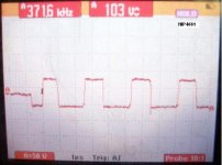
For a long time break now I returned to my class-d amp. It is very bad to say one channel of my HIP4081 chip smoked. I got some scop results with the working CH but, i think the smoked ch burnt something inside the chip and the IC does not work properly. So the output sq wave is not in 50% . Any way my friend brought the mobile Fluke for an hour and I got these photos. More masurements will be done next weekend by changing the IC with new one.
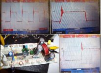
I also tested 2113 ( 4069 for triwave+ LM311+4070+2113 and IRF640 for output) and got the scop results. The test was made on a board and all the circuit on board with single 12V supply. There are some spikes but, the circuit built on a bread board and no snubbers on output mosfet. So, it is normal I think.
Hi Luka et all.
For a long time break now I returned to my class-d amp. It is very bad to say one channel of my HIP4081 chip smoked
. I got some scop results with the working CH but, i think the smoked ch burnt something inside the chip and the IC does not work properly. So the output sq wave is not in 50% . Any way my friend brought the mobile Fluke for an hour and I got these photos. More masurements will be done next weekend by changing the IC with new one.I also tested 2113 ( 4069 for triwave+ LM311+4070+2113 and IRF640 for output) and got the scop results. The test was made on a board and all the circuit on board with single 12V supply. There are some spikes but, the circuit built on a bread board and no snubbers on output mosfet. So, it is normal I think.
Attachments
Hi
Great, it works, well at least one does fully. What you must remember is to put alot of C for IR output drive, not that important for vcc/vdd. So 100uF for vcc/vdd is ok, but just to be save try to have 100uF normal(elko) + 22uF tantal for low an high side drive. I have that much, and what way I can't destroy my IR or fet if the amp would clip at output.
You use 4069 for what? Also I don't know if LM311 is what fast for use in D amps, well you know by now, so I guess it is.
Will you start to make boards?
Hi,
Yes I'll start but to make boards.But i gave up daughter boards. Why? Because when one uses daughter boards it is difficult to ensure short tracks between the mosfets and driver IC. But, it is usefull to make a daughter board for tests.
Did you see the output wave form of HIP4081? It is disappointing that the output has 103V pk to pk before LC filter. And 4081 only can work up to 80V. Although my power supply is +/-35V ,I saw this 103V on the output. My bench SMPS converts 12V to +/-35V and can handle up to 400W. But now it has a 10A projection car fuse on input. Therefore, it can not give much more than 120W or so.
Hýýým my pcb component lay out enclosed. Not final, it is the last version before the final one. Final one on my home PC.
I will also desing a d-amp with 2113 and will make boards for it.
4069 for triwave osc ( third of inverters for triwave, see AN9405 on the link below). Plus something, I am planning to use the left 3 inverters inside the 4069 to ensure dead time instead of RDC network. What do you think?
http://www.intersil.com/data/an/an9405.pdf
Regards
Yes I'll start but to make boards.But i gave up daughter boards. Why? Because when one uses daughter boards it is difficult to ensure short tracks between the mosfets and driver IC. But, it is usefull to make a daughter board for tests.
Did you see the output wave form of HIP4081? It is disappointing that the output has 103V pk to pk before LC filter. And 4081 only can work up to 80V
. Although my power supply is +/-35V ,I saw this 103V on the output. My bench SMPS converts 12V to +/-35V and can handle up to 400W. But now it has a 10A projection car fuse on input. Therefore, it can not give much more than 120W or so.Hýýým my pcb component lay out enclosed. Not final, it is the last version before the final one. Final one on my home PC
. I will also desing a d-amp with 2113 and will make boards for it.
4069 for triwave osc ( third of inverters for triwave, see AN9405 on the link below). Plus something, I am planning to use the left 3 inverters inside the 4069 to ensure dead time instead of RDC network. What do you think?
http://www.intersil.com/data/an/an9405.pdf
Regards
Attachments
HI
Use RDC network. Why? instead of R put trimer = pot, so you can adjust dead time for both sides. How did that 103V get there? Do you have any decoupling cap cross supply? like 470nF one? I would also use 4060 for generating triangle, I can already here you say why, well fixed freq., able to synchronize it with smps or other amp,... it is constant so you don't need to worrie that it will change during music playing....
PS: Damn board will look great, can't wait to see it...
- Status
- This old topic is closed. If you want to reopen this topic, contact a moderator using the "Report Post" button.
- Home
- Amplifiers
- Class D
- Stereo Class-D amp HIP4081