
(available from Ebay seller Audiotek *** - a wellknown scammer)
Well I received my first Audiotek package finally. Got 3 more packages being shipped.
Packed in a little plastic storage case (various Wima caps). Everything fine but the smaller wima's, 0.47uJ100 do not have Wima written on them. Still the same colour but not sure if they are fakes.
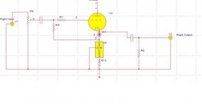
Modified circuit with the CCS LM317. Really not sure if its incorporated correctly for a CF.
Have a designed this correctly?
Attachments
Brit01 said:Thanks Eli.
Was this what you had in mind?
Yes, it is. However, I have not changed my mind about 10M45S vs. LM317.
Maybe a dumb question.
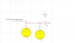
I am building a simple CF (point to point) with Bas's psu to supply the B+ to 2 x 6N1P's.
I'm unsure of the connection of the B+ to the plate pin 1.
Do I need a cap running to ground before pin 1 or can it be a direct connection from the B+ out of Bas's psu to pin 1?
I am building a simple CF (point to point) with Bas's psu to supply the B+ to 2 x 6N1P's.
I'm unsure of the connection of the B+ to the plate pin 1.
Do I need a cap running to ground before pin 1 or can it be a direct connection from the B+ out of Bas's psu to pin 1?
By "Bas' psu" I assume you mean the power supply that was in the Aikido PCB group buy? Then no, you don't need another filter cap, there is already one at the output (after the resistor).
Hi leadbelly. Yes the psu from his Aikido group buy.
Looking at the schematic below I can omit C1 then?
Also I see on JB's Aikido design he has a cap, C6, to ground from B+ before the plate. What is the purpose of this?
Attachments
Me I also experimentally converted my 6V6 pre amp in to CF during a course of experiments with active loadings, both CCS and gyrator as common source. Since I have a capacitor-less B1 to compare too, I thought it would be nice to know how it does as a buffer. For the moment, it runs on 328V regulated B+, 5K 10W Rk, 183V, 30mA across each tube. At 145V cathode it does not need filament lift since the 6V6 has a 200V max spec for difference to heater. I use the new Tungsol bottles. The input cap is a 33n K-72 Teflon, and its enough, because I bootstrapped the grid for bias and its in to several MegOhm region. The 6V6s are triode strapped via 120R carbon 1W. The 0.9X gain is enough for me because I run a 28dB KT88 triode P-P amp on 95dB speakers, its very silent, the big for the situation, heretically used output tubes as line elements are not microphonic in CF as in common cathode, and all in all it kills B1 on the spot for boldness and expression and drive. CAD gives about 190 Ohm output impedance as it runs now at 5W per bottle. I want to try active cathode sink too.
athos56 said:Isn't that to provide decoupling between the halves of the tube?
No, it's part of the power supply, and it's normally drawn as part of the supply. It reduces ripple by shunting it to common. Since the plates are tied together in a common node, it cannot affect one differently than the other.
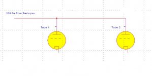
Brit01 said:The B+ supplying the anode of 2 tubes is shown below.
Do I need to add a cap to ground between the B+ output and the anode of each tube or is it fine as shown?
Looking at the Aikido I see he has C5 to ground.
See above. If the power supply has that cap, then use it, or expect more 120Hz noise. If the supply has a common output for both channels, then one cap is used. If the supply has split outputs, i.e., a separate parallel resistor or inductor for each channel, then each should be followed by a cap.
If you are going to cite a component number from a specific circuit, please provide a link to the circuit.
Sheldon
a simplistic buffer
May be a bit off-toppic, because I use 2 triodes in a Broskie CF with symetrical PSU .
Using 2 x 6NP, Rk is 300 Ohms, B+ and B- are 90v
The main advantage is that the input can handle a DC offset from sources (where you may skip any output caps), only 2 resistors and a cap on the signal path !
R.C.
May be a bit off-toppic, because I use 2 triodes in a Broskie CF with symetrical PSU .
Using 2 x 6NP, Rk is 300 Ohms, B+ and B- are 90v
The main advantage is that the input can handle a DC offset from sources (where you may skip any output caps), only 2 resistors and a cap on the signal path !
R.C.
Attachments
CF in action
I have just built this simple CF, no CCS, just curious to know how these sound.
6N6P tubes. B+ 240V
Do the voltages look ok?
Got about 10.6 mA on the cathode.
It is sounding very clear and detailed, bit of hiss from the right but the breadboard is a bit messy.
What are your opinions in regards to the values here?
I realise the bottom cathode resistor needs to be of high wattage as these get hot.
Attachments
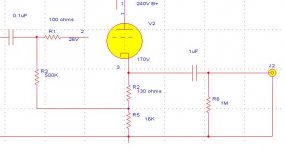
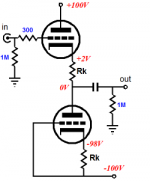
I believe the voltage at the grid should be much higher, in the region of 140V as I have 170 at the cathode and 240 at the anode.
eg:
"In this case the load line indicates that the voltage across the valve is 140V. The cathode voltage must therefore be HT-Vak = 280-140 = 140V. The grid voltage must be 140+(-3.4) = 136.6V"
Do I reduce the value of the 500K resistor to grid to increase the Voltage?
eg:
"In this case the load line indicates that the voltage across the valve is 140V. The cathode voltage must therefore be HT-Vak = 280-140 = 140V. The grid voltage must be 140+(-3.4) = 136.6V"
Do I reduce the value of the 500K resistor to grid to increase the Voltage?
Update:
I built the CF with 6N6P. Very nice sound. Good punch and bass notes. I liked this a lot. 1.7 V drop. 250 V B+. 14mA (160V on cathode with 10K cathode resistor).
Now this evening I changed for a 5687. 10mA current. 235 B+.
1.3 Voltage drop.
Very different indeed. Quite a bit more treble. Brighter sound. Maybe a tad less bass. Very detailed and dimensional.
Using RTI 1uF output cap.
Still I was a little confused on how to wire the heater of the 5687 with a 12.6V tranny. I've got it connected to pin 4 and pin 5. Pin 8 not connected. Tell me if I have this wrong.
Playing from a CDP Rotel 965.
Power amp Carver TFM-55. Klipsh F1.
output resistor to ground question
I just built my first chassis to a CF buffer.
When I tested it it had no bass. I couldn't believe it.
Then I realised I misplaced the 1M resistor to ground after the output cap.
Can someone explain the concept here? Why did the bass return with this resistor?
What effect changing the value of this resistor have on the output?
Cheers
- Status
- This old topic is closed. If you want to reopen this topic, contact a moderator using the "Report Post" button.
- Home
- Amplifiers
- Tubes / Valves
- Stereo Buffer with a single twin triode