Hi Statics Man,
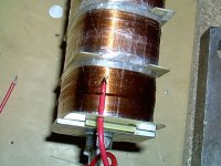
Thanks for sharing your transformer design.
Wachara C.
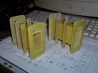
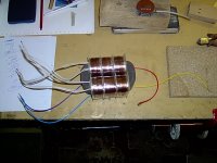
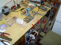
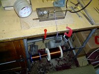
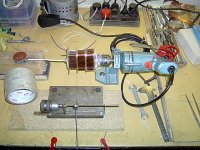
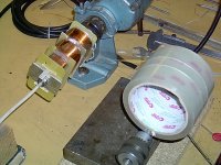
Glad to help you. Here are some more Photos.
Attachments
-
 IM000607.JPG56.9 KB · Views: 519
 -
 IM000702.JPG60.5 KB · Views: 515
 -
 IM000665.JPG63.4 KB · Views: 513
 -
 IM000667.JPG61.1 KB · Views: 499
 -
 IM000668.JPG62 KB · Views: 498
 -
 IM000675.JPG62.2 KB · Views: 207
 -
 IM000694.JPG62.9 KB · Views: 216
 -
 IM000690.JPG62.1 KB · Views: 171
 -
 IM000687.JPG60.6 KB · Views: 191
First winding attempt
Hi,
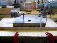
I just tried to wind my first transformer on a EI84 core. At first, all worked out as intended. I stoppet the winding from time to time to inspect and all was fine.
Then I ran the winding machine and passes 1500 "double turns" (winding with 2 strains of wire on the secondary) and stopped to inspect.

I saw that a turn had skipped the bobbin an coiled around the axle of the winding machine. Had to discard the whole secondary winding and start over...that will be an other day
On top of that, it seems like it will be a very tight fit to have 4800 turns on the secondary on that core. Aiming for a 1:120 ratio with 40 turns on the primary.
Regards
Bent
Hi,
I just tried to wind my first transformer on a EI84 core. At first, all worked out as intended. I stoppet the winding from time to time to inspect and all was fine.
Then I ran the winding machine and passes 1500 "double turns" (winding with 2 strains of wire on the secondary) and stopped to inspect.
I saw that a turn had skipped the bobbin an coiled around the axle of the winding machine. Had to discard the whole secondary winding and start over...that will be an other day
On top of that, it seems like it will be a very tight fit to have 4800 turns on the secondary on that core. Aiming for a 1:120 ratio with 40 turns on the primary.
Regards
Bent
second:the meter i have only reads ac average and not true rms which was throwing me way off from my scope readings.but the pics are true and i was getting 600v plus at 300hz and above and flat to 10khz with a drop to 20khz of not more than -1.5db,with only 10 turns for a primary
my study has found that a toroid power transformer will work very well to drive an esl by just winding a new primary to get a desired ratio.this will only work in a hybrid system unless you have a realy realy big core.
Hello Jerry,
Congrats on improving your measurement setup and getting things to match up better with your anticipated results.
Not sure if you caught Calvin's suggestion for you concerning your primary windings in post #159 on your other thread.
http://www.diyaudio.com/forums/planars-exotics/158115-material-esl-16.html#post2087071
Basically, if you want to use the existing 120V windings as your secondary and plan to use a small number of primary turns, like 10, to get the step up ratio you desired (70, I believe) then the bandwidth will be limited on the low end by the resulting low inductance and possibility of saturation. On the high end, you are limited because of the poor coupling of the small 10 turn section to the 360 degree coverage of the secondary on the core.
Calvin's suggestion is to wind multiple section of 10 turns and hook them up in parallel. The primary inductance will be the same, so your low end impedance will be the same. Also, the step-up ratio will be the same. But, the leakage inductance will be reduced by approximately the square of the number of sections you put in parallel. Just adding one or two more sections should easily push your bandwidth above 20kHz even with the capacitive load of your panel added.
Give it a try, you will like the results!
Last edited:
thanks bolserst,yes i did, and i followed his advice.i have already made one data chart using my scope and as of this moment i'm making another one using my cheapy digital VOM to compare it too, i am also writing the process to post, hopefuly by tommorow.thanks again! jer
Last edited:
Hi,
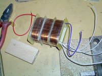
I also find out that by reducing the coil covering area from a full circle to half or a quarter of a circle on a toroid makes a lot of difference to high frequencies. I guess you can tailor the coil capacitance by adjusting the coil coverage area. With less area but the same number of turn, high frequencies can go higher.
Wachara C.
yes, i think i have noticed this.i wil investagate this further.my 10khz to 20khz seemed to go from -.9db to -1.25db or -1.6db or more.using all of 40 turns as 10 turns.i used .01 uf 6kv cap on one 120v winding in all of the test except the 10 turn one. because it presented less than a 8 ohm load above 200hz and the amp would shut down immediately at any voltage.
New cores in order
Hi,
I found a local transformer manufacturer today who was more than willing to supply me with laminations, coilformers and the lot for a very modest charge!
laminations of type EI120/40 which is 120mm wide, with a core of 40mmX40mm
I guess this core will be big enough to hold 40 primary turns X 3 and 4800 secondary turns.
Regards
Bent
Is it grain-oriented iron? Remember that there is a huge difference in sound quality, especially in high freq's, between thick ordinary power transformer laminations and thin grain-oriented ditto!
That is great, bentl! However jonas is very correct.You must pay close attention to the material type and especialy the lamination thickness.The thinner material reduces the eddy current losses,m4 or m6 material is what to look for as m6 being the best.But as the laminations get thinner and the quality goes up unfortunately so does the cost.But it is a great place to start.I would get some and try it out.It might just work for your needs. jer
Hi,
the material quality is stated as M330-50A
manufacturer is Elektro-Bauteile-Katalog der Fa. Gebr. Waasner GmbH
Not sure if it is grain oriented or not.
Regards,
Bent
the material quality is stated as M330-50A
manufacturer is Elektro-Bauteile-Katalog der Fa. Gebr. Waasner GmbH
Not sure if it is grain oriented or not.
Regards,
Bent
Hi,
the material quality is stated as M330-50A
manufacturer is Elektro-Bauteile-Katalog der Fa. Gebr. Waasner GmbH
Not sure if it is grain oriented or not.
Regards,
Bent
M330-50A is CRNGO Cold Rolled NonGrain Oriented.
Cancel that!
Hello fellow diy’ers, are you ready to determine the saturation level of your new core?
The reason I say this is because this method applies to all types, shapes and sizes of core material.
For instance, let say you had two stacks of E-I material of the same type and size and you wanted to combine them together as one stack (one of my back burner projects).
Because, as you know that doubling the cross sectional area, quadruples the power handling of the transformer (how’s that for something for nothing).
Rather than wasting time with the calculator, charts and figures, that you’re not sure if, and or, it applies to your core material. The easiest way to find out is to go ahead and just test it.
You don’t need anything more than the core that you are working with and one winding.
No high turn interleaved double laminated secondary is needed here!
I have already described the test setup earlier so no need to waste time.
So, let’s get testing
Methodology:
I originally chose to test turns in multiples of 5’s (10,15,20,25 exec). first I started with 10,20,30 and 40 turns. Then when I added an extra 5 turns to test 15 and 25. I then realized by the data, that I saw a pattern that the 15 turn data was exactly in the middle of 10 and 20 turn data and could be found by averaging the two adjacent sets (10 and 20) of data to get the results of 15 turns.
To prove this I went ahead and tested 25 turns and found this to be true also with 25 turns. I found this to be too repetitive .as I did each test probably five time, each, to make sure it was correct (a small price to pay for science).
I’ll explain this later when we look at the charts. First we must get the data.
The setup:
You connect the output of your amplifier to the winding that you’re testing, also your scope and voltmeter to the same winding as well. Make sure the signal generator is turned down so that there is no signal.
Set the generator at say 1khz to 3khz or so, the higher the better, if you like, just as long as it is in the audio band. Make sure it is also set for a sine wave.
Now, you turn your amp up all the way (yes I said to 11) and slowly turn up the signal generator, watching the scope until you get a slightly clipped sine wave.
Then back it down slowly until you see a pure sine waveform on the scope.
Don’t worry you won’t hurt the amp. Once you get used to this process you will understand.
There will be times the amplifier may overload and the built in protection may kick in and you’ll have to reset it. But make sure that you turn down the signal first before you turn it back on.
Once you get a clean sine wave at full power record the voltage on the meter. This is the maximum voltage your amp can produce. If you have a really big amp you might want to limit your voltage (with the master volume control) to 20Vrms to 50Vrms on the meter. An 80V peak-to-peak signal on the scope is 28.283Vrms on the meter and means 100 watts into 8 ohms. some meters only read ac average and not true rms.
This may confuse you when you’re comparing the levels to the scope.
Ignore this and only use the readings on the meter for your results. I’ll explain why in a moment.
It is best that your meter reads down to .01 (10 millivolt) or .001(1 millivolt) for accuracy but you can get by with .1-volt resolution, as you will see in the charts I did.
Here’s how:
It is very simple really
I used the following frequencies to test with, 10hz through 100hz in increments of 10hz and 100hz through 1000hz in increments of 50hz.
Although I never got to 1000hz .you could, based upon the size of the core and the minimum number of turns you are testing.
Basically you start with setting your signal generator set at 10hz and the level set to 0.
Then bring the signal level up, slowly, as you watch your scope, until you see a waveform.
Throughout this process you will have to keep adjusting your scope in order to get a large and stable display that is good enough for you to analyze with your eyes.
This becomes very tedious after awhile. So, please be patient and take the care to get accurate readings.
You may also find that once you recognize a pattern in your data, you may end up going back over it to recheck and correct some of your data. As I did!
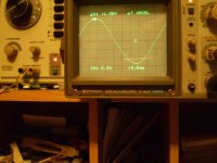
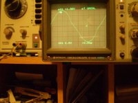
As you start reaching saturation you will notice that the sine wave will become slightly distorted. This I call the edge the edge of saturation.
If more level is applied then the core will be completely saturated and you will have a severely distorted sine wave.
This could cause the amp’s self protection circuit to trigger and shut down as this is creating a tremendous load on it. If this happens just back off the level and reset your amp.
What you want to do here is to get the highest level you can without any deformities in the sine wave.
Once this is achieved record the voltage level shown on the meter in your chart. Then move on to the next frequency.
Starting over from the beginning. Repeat this process for every frequency and do it all over again when you change the number of turns.
At some point in time you my get values that seem to high, this is normal .the only way around this is to use a THD analyzer so just eyeball it the best you can. Like I said you may end up going back, rechecking and changing the data.
The only important thing here is that you want to be right at the edge, or just below the edge of saturation.
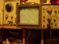
Whichever level you choose just try to be consistent that’s all that counts. I have included some pic’s to give you an idea of what to look for on the scope.
Using a load:
In my tests I choose to use a .01uf 6 kV capacitor connected to one of the 120V windings to simulate a worst-case load. This didn’t seem to affect any of the results, with or without it.
Except for the 10-turn test .As the capacitive reactance that was reflected was less than an 8-ohm load above 500hz .My particular amp (a cheapy) did not like this at maximum power. It would shut down and did so, quite often, throughout the tests.
But it did not damage it in any way. It still works and still sounds excellent.
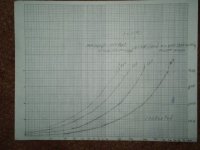
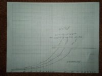
Charting your data:
I used a semi log graph to chart my data. Using a log scale for the frequency, and a linear scale for the voltages. It doesn’t really matter which one you use just as long as you understand them. I posted my charts as well to show as an example.
In the next article I will discuss the charts and the relationships between the data and how to use them.
Have fun until next time! Jer
The reason I say this is because this method applies to all types, shapes and sizes of core material.
For instance, let say you had two stacks of E-I material of the same type and size and you wanted to combine them together as one stack (one of my back burner projects).
Because, as you know that doubling the cross sectional area, quadruples the power handling of the transformer (how’s that for something for nothing).
Rather than wasting time with the calculator, charts and figures, that you’re not sure if, and or, it applies to your core material. The easiest way to find out is to go ahead and just test it.
You don’t need anything more than the core that you are working with and one winding.
No high turn interleaved double laminated secondary is needed here!
I have already described the test setup earlier so no need to waste time.
So, let’s get testing
Methodology:
I originally chose to test turns in multiples of 5’s (10,15,20,25 exec). first I started with 10,20,30 and 40 turns. Then when I added an extra 5 turns to test 15 and 25. I then realized by the data, that I saw a pattern that the 15 turn data was exactly in the middle of 10 and 20 turn data and could be found by averaging the two adjacent sets (10 and 20) of data to get the results of 15 turns.
To prove this I went ahead and tested 25 turns and found this to be true also with 25 turns. I found this to be too repetitive .as I did each test probably five time, each, to make sure it was correct (a small price to pay for science).
I’ll explain this later when we look at the charts. First we must get the data.
The setup:
You connect the output of your amplifier to the winding that you’re testing, also your scope and voltmeter to the same winding as well. Make sure the signal generator is turned down so that there is no signal.
Set the generator at say 1khz to 3khz or so, the higher the better, if you like, just as long as it is in the audio band. Make sure it is also set for a sine wave.
Now, you turn your amp up all the way (yes I said to 11) and slowly turn up the signal generator, watching the scope until you get a slightly clipped sine wave.
Then back it down slowly until you see a pure sine waveform on the scope.
Don’t worry you won’t hurt the amp. Once you get used to this process you will understand.
There will be times the amplifier may overload and the built in protection may kick in and you’ll have to reset it. But make sure that you turn down the signal first before you turn it back on.
Once you get a clean sine wave at full power record the voltage on the meter. This is the maximum voltage your amp can produce. If you have a really big amp you might want to limit your voltage (with the master volume control) to 20Vrms to 50Vrms on the meter. An 80V peak-to-peak signal on the scope is 28.283Vrms on the meter and means 100 watts into 8 ohms. some meters only read ac average and not true rms.
This may confuse you when you’re comparing the levels to the scope.
Ignore this and only use the readings on the meter for your results. I’ll explain why in a moment.
It is best that your meter reads down to .01 (10 millivolt) or .001(1 millivolt) for accuracy but you can get by with .1-volt resolution, as you will see in the charts I did.
Here’s how:
It is very simple really
I used the following frequencies to test with, 10hz through 100hz in increments of 10hz and 100hz through 1000hz in increments of 50hz.
Although I never got to 1000hz .you could, based upon the size of the core and the minimum number of turns you are testing.
Basically you start with setting your signal generator set at 10hz and the level set to 0.
Then bring the signal level up, slowly, as you watch your scope, until you see a waveform.
Throughout this process you will have to keep adjusting your scope in order to get a large and stable display that is good enough for you to analyze with your eyes.
This becomes very tedious after awhile. So, please be patient and take the care to get accurate readings.
You may also find that once you recognize a pattern in your data, you may end up going back over it to recheck and correct some of your data. As I did!
As you start reaching saturation you will notice that the sine wave will become slightly distorted. This I call the edge the edge of saturation.
If more level is applied then the core will be completely saturated and you will have a severely distorted sine wave.
This could cause the amp’s self protection circuit to trigger and shut down as this is creating a tremendous load on it. If this happens just back off the level and reset your amp.
What you want to do here is to get the highest level you can without any deformities in the sine wave.
Once this is achieved record the voltage level shown on the meter in your chart. Then move on to the next frequency.
Starting over from the beginning. Repeat this process for every frequency and do it all over again when you change the number of turns.
At some point in time you my get values that seem to high, this is normal .the only way around this is to use a THD analyzer so just eyeball it the best you can. Like I said you may end up going back, rechecking and changing the data.
The only important thing here is that you want to be right at the edge, or just below the edge of saturation.
Whichever level you choose just try to be consistent that’s all that counts. I have included some pic’s to give you an idea of what to look for on the scope.
Using a load:
In my tests I choose to use a .01uf 6 kV capacitor connected to one of the 120V windings to simulate a worst-case load. This didn’t seem to affect any of the results, with or without it.
Except for the 10-turn test .As the capacitive reactance that was reflected was less than an 8-ohm load above 500hz .My particular amp (a cheapy) did not like this at maximum power. It would shut down and did so, quite often, throughout the tests.
But it did not damage it in any way. It still works and still sounds excellent.
Charting your data:
I used a semi log graph to chart my data. Using a log scale for the frequency, and a linear scale for the voltages. It doesn’t really matter which one you use just as long as you understand them. I posted my charts as well to show as an example.
In the next article I will discuss the charts and the relationships between the data and how to use them.
Have fun until next time! Jer
Attachments
M330-50A is CRNGO Cold Rolled NonGrain Oriented.
Cancel that!
If the laminations are under 0.3 mm thick (and not to costly), do a test winding and listen, there is a chance that the sound is alright....
has any body tried this http://www.antekinc.com/pdf/AN-64115.pdf for $69. jer
If the laminations are under 0.3 mm thick (and not to costly), do a test winding and listen, there is a chance that the sound is alright....
Hi,
I will wind the transformers on the low-grade cores and test. It is easy to swap cores to a higher grade later if needed.
The order was already shipped and they didn't have that lamination in other qualities.
Regards
Bent
- Status
- This old topic is closed. If you want to reopen this topic, contact a moderator using the "Report Post" button.
- Home
- Loudspeakers
- Planars & Exotics
- Step-up transformer design