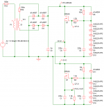
In Zen version 3, Nelson details a power supply. My question is this: can two positive voltage power supplies, such as described in the Zen article, be stacked, piggy-back?
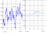
I'm submitting a schematic that I simulated. According to Simetrix, the voltage is smoothed considerably with the second stage.
I'm seeking this particular method because I wish to use higher voltage (125v) on my mid-stage mosfets. I'm not very comfortable operating a chip voltage regulator at this extreme.
Attachments
KevinHeem said:Is what you created a capacitance multiplier-multiplier.
Hahahaaa....
I think you're right...
KevinHeem said:Yes, can you explain it to me!
The first stage has voltage variations of 0.120 volts, while the second stage only has variations of 0.005 volts.
woody said:Because the input impedience of the pass mosfet is so darn high
there might be less noise if you replaced the R34 resistor with
a ccs and replaced the zener stack with a resistor. No zener =
no zener noise.
The zener stack is what holds the voltage constant. Get rid of the zener stack and the voltage varies, yes?
KevinHeem said:Thanks, can you simulate the circuit with higher values for C5 and C6 to see what happens?
The problem with increasing the values of C5 and C6 is that high voltage caps are expensive. I'm trying to keep this thing affordable.
If you have a cap in mind that will do the trick, let me know...
")
carpenter said:
The problem with increasing the values of C5 and C6 is that high voltage caps are expensive. I'm trying to keep this thing affordable.
If you have a cap in mind that will do the trick, let me know...
Ah yes, you're running in the 125v range, I'm just running in the 50v range. Really don't have anything in mind, have just been curios what changing these values would do. Thanks Carpenter
No replace r34 with a CCS such as a CCS diode using a 10ma CCS instead of the 15k resistor r34 then select a resistor value to use instead of a zener stack. In this case 10ma across a 4k resistor will give you a 40v across the 4k resistor. In this example
any input voltage between ~43v and ~143v (assuming a 10ma
CCs diode with a 100v complience rating) will give 40v across the
4k resistor.
any input voltage between ~43v and ~143v (assuming a 10ma
CCs diode with a 100v complience rating) will give 40v across the
4k resistor.
Hello Carpenter, I am looking at your circuit, and also your post about higher voltage caps being expensive. From the circuit, it looks like you are using 220uF caps, I am assuming they are electrolytics. These seems pretty cheap to me. As an example, I checked out Antique Electronic Supplies and they have 220uF caps rated for 300 VDC from Illinois Capacitor for $4.75ea.
Peace,
Dave
Peace,
Dave
I did a bit of searching and found reasonably priced 1000uF electrolytics at Digi-Key. Panasonic caps are $3.57 each if I purchase in lots of 10. Quite doable.
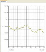
The only cap that made a world of difference (according to the sim) was C5 and C2 (I'm re-posting the schematics in case something has changed).
I'm filtered down to just a tad over 1mV with a two stage regulator.
The only cap that made a world of difference (according to the sim) was C5 and C2 (I'm re-posting the schematics in case something has changed).
I'm filtered down to just a tad over 1mV with a two stage regulator.
Attachments
- Status
- This old topic is closed. If you want to reopen this topic, contact a moderator using the "Report Post" button.
- Home
- Amplifiers
- Pass Labs
- Stacking power supplies