What things are you trying to achieve? What are your loudspeaker model(s). Do you need all the power that UL will deliver? Are you merely trying to take out all the parts you can, in order to simplify the amp? i.e. 'simple is better' theory. How closely does your amp follow the Dyna circuit and tube selection (other than the fact that you are using a different output transformer)?
The Dyna ST70 was built to a practical price and performance point. It had positive synergy, worked better than it should have (just a little like the bumble bee that is not supposed to be able to fly, but flies anyway). In its day, it was able to satisfactorily drive a number of different kinds of loudspeakers, and please many listeners.
Decades ago, there was a simple mod that took little effort and time, but made the Dyna ST70 run circles around a whiz-bang solid state amp of the day. I have an idea what that mod might have been, it would have reduced the maximum output power, but given the amp more finesse. The 'listening event' was written up in "The Soul of Sound" a book by Lynn Olson. The Soul of Sound is a very interesting read.
Last edited:
Of course it does, this is analog electronics: everything affects everything else.Does the connection point of the feedback capacitor have any effect on its phase compensating characteristics?
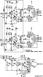
I finally looked at the Dynaco ST70 schematic to see what the H___ was going on here. Very interesting. I'm not so sure this UL to 7199 cap is -directly- being used to equalize the splitter at HF (even though the manual says that, and the net effect may lead to that). This is just a local NFdbk loop that progressively shifts the global N Fdbk gain to a local N Fdbk loop at HF. The loop gain available to the global loop is eaten up by the interior local loop at HF. The UL tap/winding section in OTs is generally well coupled to the secondary for UL Fdbk purposes, so this is a good place to monitor the primary. (as long as it is stable, there is still some leakage L between plate and UL tap)
I am surprised however that a series resistor is not used with the 390 pf cap to set a transition frequency. It would -appear- that the Dynaco setup is transitioning across the entire audio band, although (hopefully) some resistance in the OT may be providing that selective freq. function up-band somewhere. One would like to keep the global N Fdbk active to as high a freq. as possible, permitted by the OT performance.
I have been thinking of building an amplifier using this approach, but with a proper differential. driver gain stage included. Two balanced UL tap N Fdbks RC coupled back to the driver cathodes. Frequency selected to still allow the most global loop N Fdbk BW possible.
One can get a little more clever and include some neg. R in the driver to cancel out the OT resistance. Lowering the output Z from the primary side. (OT resistance is quite constant, so this can be set and forget.)
Can get even a little more clever and put some neg. L in the driver stage to cancel the OT leakage L too. (leakage L being a quite constant winding air path effect per OT, maybe some differences between "identical" OTs) Thus accomplishing everything on the primary side that is normally considered global Fdbk territory.
Low drive impedance from the output tubes from local N Fdbk also handling the magnetizing current.
If the neg. L is synthesized in the driver circuit by a small core with the same magnetic material properties as the OT core, it can even compensate directly for the OT magnetizing current. (the output tubes still have to provide that extra magnetizing current, but the local N Fdbk loop will not have to actively correct for it much then, being already programmed in from the driver)
No attempt to cancel the speaker resistance or L, which is too variable.
Trimpots used to set the neg. Z compensation to levels before instability sets in. The global N Fdbk loop has the final say, but hopefully it no longer has much corrective work to do.
.
Attachments
Last edited:
This frequency selective local N Fdbk scheme is quite rare I believe. Most audio amplifiers are built as simple as possible, mostly copies of a few basic designs. I only now realized Dynaco had used this trick.
Here is one complex symmetrical lab amplifier that seems to use this technique (C122 and C?). Schematic below is from the original design patent. And the original designer is still selling audio amplifiers I believe. H. Wolcott.
http://www.diyaudio.com/forums/tube...ac-lab-grade-audio-amplifier.html#post4707110
hermann Wolcott tube amplifier - Google Search
Placing the Dynaco ST70 390pF local feedback cap to the UL tap works better -IF- the OT supports low phase shift from the plate to the UL tap. Otherwise going to an output tube plate is the safer way, but less distortion reducing. (since the UL tap is typically closer coupled to the secondary)
Most of the shunt "Schade" N Fdbk designs around use the plate tap. But I have measured some low cost OTs that had -one- (an outer layer wind of the OT) of the two plate windings poorly coupled to the secondary, due to minimal interleaving. Could make for some -interestingly- poor shunt "Schade" designs.
So it all depends on the quality of the OT. One would really like to see a dual (or split) bobbin symmetrical OT windup for Fdbk symmetry.
Would be interesting to compare the dates of the Optimation patent and the Dynaco ST70 (or earlier similar) design introduction. They might both be preceded by a tube research journal article.
.
Attachments
Last edited:
The Henry Wolcott White Pages are available here:
H wolcott ny 2015 10 by test - issuu
Very hard to read though. Wish it could be downloaded and printed.
It appears that the Wolcott design also uses the negative resistance idea to null out the OT winding resistance. Adjustable on the front panel, can even null the speaker resistance. Although I think it is being done through the global loop, not the local loop I mentioned above. Still reading. This guy was light years ahead of most audio designers.
Hard to read, hope it mentions techniques used in the Wolcott OTs.
------------------------------
On Zobel networks for the OT secondary, see "Valve Amplifiers" by Morgan Jones 4th edition, pages 290 and 502-503
Seems like a good idea if done correctly. Stops HF ringing in the OT and improves stability of the amplifier (compensated load Z) at HF, for real speaker loads.
Last edited:
I agree with the mention above that says the best connection for the HF loop, UL vs Secondary, depends on the particular output transformer you use.
And of course, the value (pF) would have to change depending on which connection is used.
That brings us back to the fact that the Hammond transformers may not be at all like the A470 Dyna transformers of the original ST70.
And of course, the value (pF) would have to change depending on which connection is used.
That brings us back to the fact that the Hammond transformers may not be at all like the A470 Dyna transformers of the original ST70.
Another thread on Wolcott:
http://www.diyaudio.com/forums/tube...ed-positive-feedback-booster.html#post4360247
http://www.diyaudio.com/forums/tube...wolcott-amplifiers-jbl-pl100.html#post4493570
From the Whitepages write-up, looks like Wolcott went to a White cathode follower front end on the audio amplifiers. Two 6922 WCF tubes, then 6GW8/ECL86 triode gain and pentode follower-driver with positive Fdbk loop, EL34 outputs. Hope to find schematics.
Last edited:
I'd be surprised if the Hammond or Edcor OTs are similar to the A470 Dyna OTs. Edcor was the one I found a poorly coupled plate winding on one side of the primary. But the secret world of OT specs are hidden from us (if any actually exist, other than Plitron). Which is why we keep getting old 50's designs, even in mega expensive commercial tube amplifiers.
I would certainly at least -try- the UL tap local Fdbk scheme with the Hammond or Edcor OTs, but be prepared to diagnose strange instabilities. (HF scope, HP 3575A gain-phase meter) On the other hand, for an Edcor with the lop-sided flapping in the breeze plate winding, the UL tap might just be the saving grace. (the fix) Once you get good voltage Fdbk from the UL taps, who cares about the outer plate windings (leakage L). If pentodes are driving them, they don't even care about leakage L. (just a little extra V headroom needed with current mode drive)
I would certainly at least -try- the UL tap local Fdbk scheme with the Hammond or Edcor OTs, but be prepared to diagnose strange instabilities. (HF scope, HP 3575A gain-phase meter) On the other hand, for an Edcor with the lop-sided flapping in the breeze plate winding, the UL tap might just be the saving grace. (the fix) Once you get good voltage Fdbk from the UL taps, who cares about the outer plate windings (leakage L). If pentodes are driving them, they don't even care about leakage L. (just a little extra V headroom needed with current mode drive)
Last edited:
I do not think the small currents from the screens are able to have much influence on the core, nor on the magnetic flux of all the primary windings, versus the plate currents.
But connecting the feedback cap to the UL tap, versus on the plate tap, does have a definite influence on the voltage that drives the cap (100% or 40%). That changes the value of the capacitance required, and would also require a change to the resistor at the feedback node of the input tube cathode circuit.
That change of the feedback node cathode resistor, would also require a change of the feedback resistor from the output tap.
Using the UL taps for Fdbk, -WITH- UL mode screen currents, will be safer using a beam tetrode/pentode versus a real pentode (EL34). Due to the lower screen currents in the beamers. But may not be necessary. Just an idea to keep in mind.
Then one could also use HV Mosfet buffers to drive the screens from the UL taps and return the screen currents back to the plates via caps. "Improved" UL.
Then lets see, we could fix up that front end too, and an LTP driver stage...
How many mods can one do on the ST70 before it is NOT a an ST70?
Then one could also use HV Mosfet buffers to drive the screens from the UL taps and return the screen currents back to the plates via caps. "Improved" UL.
Then lets see, we could fix up that front end too, and an LTP driver stage...
How many mods can one do on the ST70 before it is NOT a an ST70?
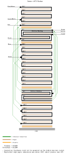
Here is an A470 OT windup diagram provided by Bob Latino here:
The Old A-470's cloth lead vs. new production outputs ...
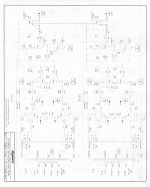
and a later Dynaco (Panor) ST160 schematic provided by Bob Latino here:
The Dynaco (Panor) ST-80 and ST-160 tube amps of the mid '90's
The A470 looks like it has the same low number of interleaves as a Hammond or Edcor OT, but has two sections with bifilar winding, presumably the part of the UL sections with matched AC to the secondary. If one were going to make an improved A470 OT today, I would put additional parallel secondary interleave sections into the design (with inter-layer insulation). The old A470 may have the same poor leakage L for the outer primary side winding as I found in an Edcor. So moving the HF Fdbk cap (lowered to 0.4 x 390 pf) out to a plate winding may not be an option, if that is the outer winding on the core.
The later ST160 is using 6550 beam tetrodes. But no sign of the HF UL local N Fdbk thru a cap to the input stages.
Interesting info:
The Optimation patent (US2652458) was filed in 1949 and granted in 1953
The 7199 tube was introduced in 1958 by RCA
The Dynaco ST70 was introduced in 1959
The Dynaco (Panor) ST160 was introduced in 1995
.
The Old A-470's cloth lead vs. new production outputs ...
and a later Dynaco (Panor) ST160 schematic provided by Bob Latino here:
The Dynaco (Panor) ST-80 and ST-160 tube amps of the mid '90's
The A470 looks like it has the same low number of interleaves as a Hammond or Edcor OT, but has two sections with bifilar winding, presumably the part of the UL sections with matched AC to the secondary. If one were going to make an improved A470 OT today, I would put additional parallel secondary interleave sections into the design (with inter-layer insulation). The old A470 may have the same poor leakage L for the outer primary side winding as I found in an Edcor. So moving the HF Fdbk cap (lowered to 0.4 x 390 pf) out to a plate winding may not be an option, if that is the outer winding on the core.
The later ST160 is using 6550 beam tetrodes. But no sign of the HF UL local N Fdbk thru a cap to the input stages.
Interesting info:
The Optimation patent (US2652458) was filed in 1949 and granted in 1953
The 7199 tube was introduced in 1958 by RCA
The Dynaco ST70 was introduced in 1959
The Dynaco (Panor) ST160 was introduced in 1995
.
Attachments
Last edited:
An interesting observation:
Changing to TV Sweep tubes requires the UL% to drop to more like 15 or 20%, due to the lower screen V used (and higher grid 2 gm). The higher plate current ability of the Sweep tubes allows the overall OT winding ratio to be dropped as well. (a low Z primary) With paralleled 24 to 30 Watt typical Sweep tubes, the UL winding will be looking close to the number of turns in the secondary winding. Allowing FULL bifilar winding of the UL sections. Similar to, but further beyond, the A470 design. (trifilar: UL1,Sec,UL2, blank, repeat... ) Additional, layer insulated, parallel secondary sections interleaved as well, to keep the full primary well coupled (although not strictly required with pentode current like drive to the outer winding sections).
The UL taps will then be like tertiary Fdbk windings. Tightly coupled to the output. Using the balanced Optimation, or ST70 like, HF local N Fdbks, and optional UL configured tubes, would produce an amplifier of
--remarkable-- performance. I wonder if this is what Wolcott used in his later "Presence" OT design. His white paper Intro remarks about the high performance OTs used.
I know how I'm going to make an amplifier OT now. Thankyou Optimation and Dyna!
Last edited:
Would 1kHz square waves be an adequate test to determine which feedback method works the best?
It will tell you something, but not really enough. If the square wave looks really bad using the plate connection, then it's probably a bad idea. However, it won't test for stability with reactive speaker loads, and it won't tell you if distortion got better or worse. Use a dummy load for testing. Putting the Fdbk connection to the plate should help over nothing connected however. (using approx 0.4 reduced cap value)
It's even likely that the UL tap will ring MORE, but produce lower output distortion in the in-band HF range. If you have a sound card FFT setup, some further tests could tell. (resistor attenuate the amplifier output for the sound card input, and use a dummy load) Measuring output sine wave phase versus input phase (at the HF end especially) across the frequency range would help a lot (with each connection tested). An FFT distortion test at some mid level sine wave would of course illuminate too.
Last edited:
The connections I would test are to the UL tap with the 390 pf cap (default), the associated plate with approx. 0.4 x 390 pf cap, and could try without the connection at all (most likely worse). The cap size has to do with the voltage magnitude at each tap. Plate will have 1/0.4 bigger signal than the 40% UL tap, so less cap needed for same N Fdbk. Could of course try with different size caps too, but that will shift the frequency where the local N Fdbk takes over. A smaller cap shifting the frequency upwards.
Last edited:
- Status
- This old topic is closed. If you want to reopen this topic, contact a moderator using the "Report Post" button.
- Home
- Amplifiers
- Tubes / Valves
- Stability question for the gurus