Can you share a schematic? I went a different route, 6SN7 driving a Russian ECC99 LTP with a CCS in the tail. I went this route for a strong LTP driver, the CCS proved to be better sounding in a previous amp.
The 6SN7 front end was for tube rolling for sound, there were so many different variants by many manufactures that I should have lots of fun collecting and trying them out. I found a Dutch site "Triode Dick" that has a similar design.
I've seen several Mosfet drivers used as LTP followers to drive the output tubes' gate when it goes positive. I have not tried this yet. Send in pics of your progress and listening impressions, and a schematic.........
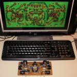
ps, Did you use the toner transfer method of PCB production?
The 6SN7 front end was for tube rolling for sound, there were so many different variants by many manufactures that I should have lots of fun collecting and trying them out. I found a Dutch site "Triode Dick" that has a similar design.
I've seen several Mosfet drivers used as LTP followers to drive the output tubes' gate when it goes positive. I have not tried this yet. Send in pics of your progress and listening impressions, and a schematic.........
ps, Did you use the toner transfer method of PCB production?
Attachments
Last edited:
More will be revealed on the design when I prove out the board I showed in the first post. The concept is DC coupled out to the output tube grids to avoid blocking distortion. There are caps at the input, as I don't entirely trust what the cruel world has to offer in terms of signal sources.
I also had to make some decisions as to how I would proceed with the output stage. I need to check the OOS output transformers I have down in the basement, but if they have the ultralinear taps, I'm probably going to proceed in that direction, with the bias supply filtered but left to swing in the same manner as the plate supply.
The Woodward-Schumacher transformer I plan to pair with this design has a 170V output meant to be used in doubler mode, a hefty center-tapped 6.3V filament winding, a 5V rectifier filament winding, and a 33V bias winding. The plan is to use the doubled B+ output for the output stage, with a regulated output from the center of the two doubler caps to feed the input. The rectifier filament winding will feed the filament of a a damper diode to delay the B+ to the output stage. I'll have some extra circuitry to delay the B+ to the input stage until the filaments are all nice and toasty. The bias winding will be doubled, for reasons that will start to become clear once I present the rest of the circuit.
There are several levels of complexity to the driver scheme that I chose, but I decided that the first implementation would have all the bells and whistles, on the assumption that it's always easier to leave stuff out rather than paste it in afterwards.The option I chose allows full-tilt class AB2 operation.
The "ST70" layout is a neat platform for experimentation in various types of driver topologies. The limited size of the driver board tends to limit excessive exuberance in terms of circuit options (the KISS principle).
Last edited:
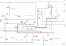
Here is a preliminary schematic for the whole shebang. The driver board contains everything up to the output of the source followers, so there shouldn't be a lot of wiring under the chassis.
This will be an experiment to determine whether I can maintain full DC coupling from the input stage plate to the output grids and maintain balance and output bias stability. I have introduced a certain amount of Blumlein "Garter" bias feedback to help center the output stage. Given the DC coupling between input and output stages, the input tubes will need matching. At present, I'm using some 5965s for input duty that have at least had some initial sorting. It'll be interesting to see how much initial mismatch I can tolerate and still have a decently functioning amp.
In extremity. I can always sling some coupling caps between the input folded cascode stage and the source followers, but I'd like to avoid that if I can. If I want to be extra heretical. I could use a servo stage for DC balancing, but I won't try that just yet.
Attachments
Last edited:
Is the common base stage to prevent capacitive loading of the LTP?
Interesting topology.
Looks like a folded cascode to me, very interesting design.
The folded cascode does a couple of things for you - first, it provides level shifting to get proper DC levels at the next stage without having to sling a capacitor or interstage transformer in between. Second, it separates the bias current through the input tube from the current flowing in the plate load, so that you can bias up the input tube for good transconductance while using a sufficiently high value of load resistor to get good gain and voltage swing.
With an easy to drive tube like the 6BQ5, the thing would probably work dandy without the source followers. The input stage would start to clip once the output tubes start to draw grid current, but without coupling capacitors, you wouldn't get blocking distortion. This might be just the thing for my other "Impostor" tube project, a venerable Lafayette integrated amplifier. I'm not particularly happy about any of its innards (from the input all the way to the output), so I plan to completely gut it with the exception of the output iron and rebuild it to my taste, even to the point of using an SMPS instead of the original transformer. And yes, I'll keep the original exterior, just to mess with people's heads.
I have similar plans for a 70's vintage Kenwood solid state receiver, keeping the lovely exterior with all the neat lights, but revamping the audio chain.
When I get around to it, I'll retool my driver board to use the 6N3P - better characteristics for my purposes, lower price. Regrettably, the pinout is different, so it's cut and jumper time for my current PCB. When the whole deal is done, I'll post pictures of my finished amp with a big "Dynaco" logo pasted on the front just to bug 20 to 20.
I've been refinishing old Dynaco ST70 output XFMRs, but have not been all that satisfied with the quality of the old guts, so I took a leap of faith and bought a pair of Triode Electronic's recreation of the ST70 output transformers. Comments re sound vs the old iron would be appreciated. Build quality looks good, but I may strip/repaint the end bells to harmonize better with my stainless chassis.
I've been refinishing old Dynaco ST70 output XFMRs, but have not been all that satisfied with the quality of the old guts, so I took a leap of faith and bought a pair of Triode Electronic's recreation of the ST70 output transformers. Comments re sound vs the old iron would be appreciated. Build quality looks good, but I may strip/repaint the end bells to harmonize better with my stainless chassis.
In word, NO...
If you look closely, the two sides are cross-coupled. This is a variant of the Blumlein "Garter" scheme for equalizing the bias current between a pair of unmatched tubes. Each side pushes up/pulls down the other to roughly equalize the bis current in the two tubes. The original scheme used cathode bias with the cross coupled feedback applied from taps on the cathode bias resistors. I was looking at using fixed bias and relatively low value cathode bias resistors.
I've fallen out of love with this scheme and won't be using it on any of my current designs. It works OK when the amp is strictly in Class A, but falls apart when one side is heavily driven and the other is in deep cutoff.

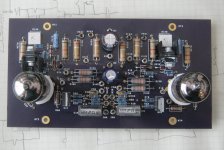
Lurid purple boards ordered from OSH_Park for eval.
I ordered this same board but never stuffed it.
I did install the tubes4hifi driver board (very similar) and liked it very much. I currently use the K&K Audio driver board and love it but feel it deserves better OPTs.
I told you they were purple... Debugging right now, as this can be done without having to integrate the driver board into the whole amp. I'll be using adjustable active cathode bias on the output stage, and will settle in on final resistor values when I get the power supply up and running.
Attachments
- Status
- This old topic is closed. If you want to reopen this topic, contact a moderator using the "Report Post" button.
- Home
- Amplifiers
- Tubes / Valves
- ST70 "Imposter"