Hi, I'm in the process of building a st-70 amp. I'm building the power supply on pcb, and i would like to use solid state rectifiers.
Has anybody tried to use a soft start delay on B+? using a mosfet?
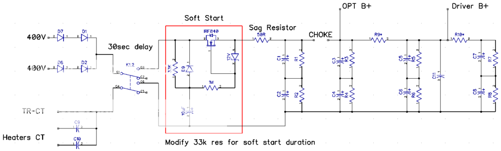
I've found the circuit outlined below on a forum i do not remember where. So i have incorporated the design on to my schematic.
Would the mosfet circuit affect the function of the amp in a bad way?
Any thoughts regarding the circuit would be very helpful.
Thanks,
Has anybody tried to use a soft start delay on B+? using a mosfet?
I've found the circuit outlined below on a forum i do not remember where. So i have incorporated the design on to my schematic.
Would the mosfet circuit affect the function of the amp in a bad way?
Any thoughts regarding the circuit would be very helpful.
Thanks,
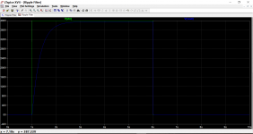
Wow, i have to install LTspice and play with it a little. I've run the simulation with Proteus and it seams there is only about 5v voltage drop. I'll probably use a higher resistor like ~80k for more smooth ramp up curve.
I thought delaying the HV a little, until the tube heaters are all hot is a good thing too.
On my simulation it seams the vdrop across de fet is only 5v. I don't know if this is the right formula to calculate the power dissipated by the fet, but i did it like this p = (0.250ma x 0.250ma) x 5v = 0.31w.
Soft start is a plus. Delayed B+ ( the relay) is without benefit, leave out.
The transistor will need some cooling, a board-mounted heatsink will do.
I thought delaying the HV a little, until the tube heaters are all hot is a good thing too.
On my simulation it seams the vdrop across de fet is only 5v. I don't know if this is the right formula to calculate the power dissipated by the fet, but i did it like this p = (0.250ma x 0.250ma) x 5v = 0.31w.
Wow, i have to install LTspice and play with it a little. I've run the simulation with Proteus and it seams there is only about 5v voltage drop. I'll probably use a higher resistor like ~80k for more smooth ramp up curve.
I thought delaying the HV a little, until the tube heaters are all hot is a good thing too.
On my simulation it seams the vdrop across de fet is only 5v. I don't know if this is the right formula to calculate the power dissipated by the fet, but i did it like this p = (0.250ma x 0.250ma) x 5v = 0.31w.
Delaying B+ is not needed as for the tubes concern. The only reason could
be to avoid overvoltage of the electrolytics before the tubes start to draw current.
Power delivered in the fet is U x I ( 5V x 0.25A = 1.25W ). Not much but some
heatsink is needed.
Are you planning to produce circuit boards with DC rectifying and softstart?
I could be interested .
Are you planning to produce circuit boards with DC rectifying and softstart?
I could be interested .
I'll be producing the board for myself with the toner transfer method. As soon as it is done i can send the design files if you want them.
i use this online calculator for making soft starter using mosfets for dc psu...http://ladyada.net/library/rccalc.html
your switch can be omitted, i see no use for it...
filaments take about 11 secs to warm up, you dimension your r c based on that...
your switch can be omitted, i see no use for it...
filaments take about 11 secs to warm up, you dimension your r c based on that...
Which circuit are you looking at ? The one in post #1 or the simulation.
Post #1 I took at face value and assumed the 400 v meant 400 volts DC. Whatever was meant or implied, the voltage fed to the FET would be rectified and smoothed and consequently there would have to be a normal reservoir cap of some description.
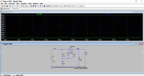
The simulation is simply simulated ripple as an 'all in one' voltage component. The 20 volts pk/pk ripple was chosen to be so high simply to highlight the effect of the ripple reduction of the circuit.
Post #1 I took at face value and assumed the 400 v meant 400 volts DC. Whatever was meant or implied, the voltage fed to the FET would be rectified and smoothed and consequently there would have to be a normal reservoir cap of some description.
The simulation is simply simulated ripple as an 'all in one' voltage component. The 20 volts pk/pk ripple was chosen to be so high simply to highlight the effect of the ripple reduction of the circuit.
I am sorry, but am i missing something?
The original ST70 uses a 5ar4 rectifier which takes almost 30 seconds before the full B+ is available. All you need is the socket , 2A of 5VAC, and the tube. So, unless your power trans is without the 5vac or enough secondary voltage, why would you bother about a slow start circuit which may give you trouble?
The original ST70 uses a 5ar4 rectifier which takes almost 30 seconds before the full B+ is available. All you need is the socket , 2A of 5VAC, and the tube. So, unless your power trans is without the 5vac or enough secondary voltage, why would you bother about a slow start circuit which may give you trouble?
I am sorry, but am i missing something?
The original ST70 uses a 5ar4 rectifier which takes almost 30 seconds before the full B+ is available. All you need is the socket , 2A of 5VAC, and the tube. So, unless your power trans is without the 5vac or enough secondary voltage, why would you bother about a slow start circuit which may give you trouble?
I'm having a very low sensitivity speakers 85db. And i would like to make the st70 with more muscle. The b+ will be around 480V and will be using KT88 as output tube. I was planing on biasing the tubes at around 55-60ma. So the consumption gets closer to the maximum rating of the 5ar4.
The GZ34 is most likely the weakest point. Replacing with Si diodes willI am sorry, but am i missing something?
The original ST70 uses a 5ar4 rectifier which takes almost 30 seconds before the full B+ is available. All you need is the socket , 2A of 5VAC, and the tube. So, unless your power trans is without the 5vac or enough secondary voltage, why would you bother about a slow start circuit which may give you trouble?
remove this weakness, and in addition B+ will raise, giving some more power.
There's probably not a whole lot of benefit to delaying the B+ as all manner of indirectly heated tubes have run for decades without it. But it surely won't hurt.
The Vdrop of the damper diode tube is high, might go against what you aim for.
But in reality you probably can not get much more power from the ST-70 than it delivers now. If you go with a "bigger tube" you are limited in two ways. First, the output iron is limited in the bass by the saturation of the core at a fixed power level, second you'll change the impedance of the plate load value by changing the B+ up and the new tube will likely have a different Z value too, so you may be able to swing more current, but you may not be able to get any more power out when tested.
Ultimately, the ST-70 is a 35watt amp. You want 3dBmore, you need to get another and strap them for mono. Going form 35 to 40 or even 45 watts will not help much in terms of real world listening.
Oddly, the opposite may work better - strapping for triode (less power measured) and now raising the B+ may work into the scheme as a benefit, as this will tend to make the clipping characteristic smoother, which works out on peaks better than UL. Gives the sonic impression of more power being available.
Drop the cathode resistor to 1/10 the value shown in the schematic - make a label on the outside near the socket changing the bias voltage reading, so you don't forget!!!. I suspect that you will find that that overall sound, especially the bass "sounds tighter".
The Dyna driver circuit is less than optimal. That's another topic. If you REALLY want more power convert the driver (new board required, probably have to DIY it) to AB2, then you will get more power.
You are right, but i'm not doing a typical st-70 build. I'm going to use edcor cxpp60-ms-4.2k for the output, and a custom toroidal transformer with higher ratings. From my understanding the damper tube will have about ~12v voltage drop. The transformer will have a 400-0-55-400 / 400ma winding.
Might as well build a different amplifier, just use the old iron... imho.
New PS iron and new output iron?
Nothing Dyna about it.
If ur not using Dyna outputs, start from scratch and build something that is actually good.
As I said AB2 is my choice. Ymmv.
The Dyna input and drive circuit is junk, no reason to keep that or the undersized Dyna chassis, you can sell that for $$... (assuming you have one).
Suddenly you are not stuck at "35 watts".
- Status
- This old topic is closed. If you want to reopen this topic, contact a moderator using the "Report Post" button.
- Home
- Amplifiers
- Tubes / Valves
- ST-70 Power supply questions