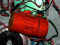
which Is that jupiter
which mkp do you recommend to use with BIB
That Jupiter is their current brown skinned higher temp line. Use something like Multicap in the Zobel.
Dual Polarity Salas
Hi Andrew / others,
Newbie here : I am building two Salas boards to create -12v 0v +12v output to power an Opamp.
Can I 'just' connect the 0v from the two boards to create a reference 0v ? or will I get current drawn from one to the other (ie: short circuit situation).
I have only single transformer 15 output to feed both boards.
Thx
Jim.
I have been trying to persuade the Group Buyers to adopt a single PCB for both the -ve and +ve regulated supplies.
With care, any of the existing PCBs can be converted to the other polarity.
I would rather buy all the PCBs identically and use the build manual to guide me to achieving which polarity I require.
But even that complication is not always required.
Simply build all -ve regulators and use a dual secondary to power the regs. This gives an equal or better performance Dual polarity regulated supply than having to buy specialised +ve & -ve PCBs and having the problem of "left overs".
Hi Andrew / others,
Newbie here : I am building two Salas boards to create -12v 0v +12v output to power an Opamp.
Can I 'just' connect the 0v from the two boards to create a reference 0v ? or will I get current drawn from one to the other (ie: short circuit situation).
I have only single transformer 15 output to feed both boards.
Thx
Jim.
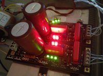
Hi, I kept building 3 boards in a row ") . My boards power TP's Opus DAC and the transceiver board. As a Vref cap, Oscon was replaced soon. Weren't a good choice there. SSLV1.1 works well, I like it very much! C105, C103 caps are Nichicon Muse KZ's: 1000 uF/25 V and 47 uF/25 V.
. My boards power TP's Opus DAC and the transceiver board. As a Vref cap, Oscon was replaced soon. Weren't a good choice there. SSLV1.1 works well, I like it very much! C105, C103 caps are Nichicon Muse KZ's: 1000 uF/25 V and 47 uF/25 V.
. My boards power TP's Opus DAC and the transceiver board. As a Vref cap, Oscon was replaced soon. Weren't a good choice there. SSLV1.1 works well, I like it very much! C105, C103 caps are Nichicon Muse KZ's: 1000 uF/25 V and 47 uF/25 V. The schematic is OK. Shows an optional Zener also that may had tricked you. Objectively yes, OSCON is a good filter. Subjectively not my preference there.
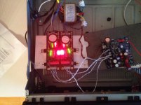
I promise you to take some pictures soon. So far I have too many LDO based (useless ) power boards close to the DAC. Also, the PLL (3,3 V) of Wolfson WM8804 , AVDD (+5 V), and AVDD(L+R) (+5 V) of WM8741 chip are powered by NewClassD regs. My BIB boards work as pre-regs (providing 1x 5,5 V, and 2x 7.0 V). Directly connected Salas BIBS are my goal  , but there are 100 nF C0G/NP0 Ceramic caps at the legs of power input of the chips. So, any advice are welcome to plan the correct output of BIB!
) power boards close to the DAC. Also, the PLL (3,3 V) of Wolfson WM8804 , AVDD (+5 V), and AVDD(L+R) (+5 V) of WM8741 chip are powered by NewClassD regs. My BIB boards work as pre-regs (providing 1x 5,5 V, and 2x 7.0 V). Directly connected Salas BIBS are my goal , but there are 100 nF C0G/NP0 Ceramic caps at the legs of power input of the chips. So, any advice are welcome to plan the correct output of BIB! Final success PSU+client application system picture we like to see as always.
I promise you to take some pictures soon. So far I have too many LDO based (useless
I have similar considerations - I have 100uF 35v Cerafine at the legs of the power input of the OPA827. I guess these are not necessary now the shunt has replaced the regulator (?) I also assume the 'sense/feed' line should be connected as close as possible to the chip power inputs (?)
I will remove these caps tomorrow and inform any difference. Oh, and maybe send a pikkie
Those have to do with local needs of the chips in the context of layout, original supply characteristics and general noise coupling if measured and analyzed best during system design. It takes objective and subjective tests to see for potential changes & differences at best one's sense and measurement gear / ability. Closest sensing helps the supply read the dynamic consumption better.
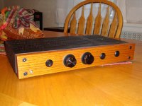
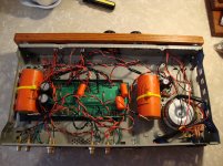
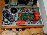
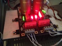
Shunts mounted on the heatsink of a donor amp. Powering a OPA827 of a DAC. DAC not final mounted yet.
Salas, can you explain to me why the LEDs of the +ve board turn off quicker than the -ve on power off ?
Salas, can you explain to me why the LEDs of the +ve board turn off quicker than the -ve on power off ?
Attachments
Last edited:
- Home
- Amplifiers
- Power Supplies
- SSLV1.1 builds & fairy tales