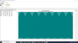
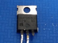
Load draws 900mA, it's enough 89mA as spare for the reg.?
Enough if 900mA is not overshot by practical load tolerance
Hi Salas,
I was trying to repurpose these old 1.1 regs for lower voltage and CCs when I kept the negative reg a bit too long without its heatsink. The three green Leds went out and I replaced Q201 which had been damaged. Now when I connect a dummy resistor along with the jumpers I cannot adjust the voltage with the trimmer pot anymore. Transformer secondaries is 15v and I have set the boards to output 13v. Here I am stuck around 10.5v. All LED's are on like normal.
In an effort to figure out the problem, I removed the jumpers and the dummy resistor. Measured 20.5V between R201 and X202-3 which seems fine and same as the reg which is working well. With power off I read opens between the G, D and S pins of Q206 so I am thinking maybe thats fine.
Any suggestions appreciated.
Thanks.
nash
I replaced Q204 the BC560c and while I was at it removed and checked Q203, 205 and 206 which checked out fine. I think my problem may also have been that I was testing with R201 that produced only 100ma while I was targeting 150ma and this was resulting in a low output V. Put a lower value resistor in R201 and the Vout immediately bumped up. All well now.
Thank you for your help.
Salas, could you explain why with 1.3 hiss at tweeter is significantly less than with the 1.1 version?
nash
Thank you for your help.
Salas, could you explain why with 1.3 hiss at tweeter is significantly less than with the 1.1 version?
nash
Hi Salas, everyone,
I bought my 1.1 BiB years ago with the mini kit and finally have to use it in my delayed project. Please let me know if my calculations are right before I order the BOM. I am using IRF610/9610 Mosfets and Toshiba K117 Jfets.
Consumption (circuit) = 80mA
CCS allowance 200mA
Q101I = 280mA
DC in = 35V
DCout = 30V
R101 = 13.2 ohms with 4 LEDs (Green), 5.7 ohms with 3 LEDs (Green) @ 4.7 V interpolated ID/VGS value.
PQ01 = 1.6W
PQ106 = 6W
R105 = 6550, so 10k trimmer
Questions
1.) What's a good example of 2.78 deg/W heatsink?
2.) Can I use 230mA (150 mA over) instead of 280mA CCS current to remedy #1 above?
3.) When calculating VA for the trafo, since I will use +/- boards side by side, minimum will be 280mA x 2 divided by 120 = ~67.2 VA?
Thanks!
Ooops, I forgot:
How do I get R103 value to plug in to the calculator?
If I am using Appendix 1, e: as I want to regulate 30V, it says 25-40V Vo Mosfet reg. 2 1.9V LED, 6.8k R303, 5K trimmer. Other parts jumper
- D101 and D102 jumpered, 2 red LEDs, and R103/R105 are 6.8k?
Thanks again!
How do I get R103 value to plug in to the calculator?
If I am using Appendix 1, e: as I want to regulate 30V, it says 25-40V Vo Mosfet reg. 2 1.9V LED, 6.8k R303, 5K trimmer. Other parts jumper
- D101 and D102 jumpered, 2 red LEDs, and R103/R105 are 6.8k?
Thanks again!
Last edited:
Questions
1.) What's a good example of 2.78 deg/W heatsink?
2.) Can I use 230mA (150 mA over) instead of 280mA CCS current to remedy #1 above?
3.) When calculating VA for the trafo, since I will use +/- boards side by side, minimum will be 280mA x 2 divided by 120 = ~67.2 VA?
Thanks!
1) Something like SK 81/ 75 SA (For USA look up Element14 parts in Newark.com)
2) Yes
3) Don't use less than 50VA ((32VAC*2*0.28*) * 1.41 for bridge rectification current spec loss) * 2 derating for cool = 50W
Example AS-0532
One more thing, I cannot seem to source the BJT's BC550C and BC560C. Any substitutes for those?
Thanks!
BC546BTA & BC556BTA
Ooops, I forgot:
How do I get R103 value to plug in to the calculator?
If I am using Appendix 1, e: as I want to regulate 30V, it says 25-40V Vo Mosfet reg. 2 1.9V LED, 6.8k R303, 5K trimmer. Other parts jumper
- D101 and D102 jumpered, 2 red LEDs, and R103/R105 are 6.8k?
Thanks again!
For +/- sections R103 R203 = 6.8k
- Home
- Amplifiers
- Power Supplies
- SSLV1.1 builds & fairy tales


 Used other power tx, before 9VAC and now 15VAC, also changed the trimmer & resistor of Vref area.