Hi,
I wonder, is there any xls spreadsheet to help with values for this version, I made a board but not exactly sure if the v1.1 xls is suitable for calculating the values.
I am looking to use it on a JFet preamp, current draw is 60mA at 24v. Filtered DC is sitting at 38.5V. Any tips for values greatly appreciated. Thanks gents.
http://www.diyaudio.com/forums/powe...w-voltage-shunt-regulator-46.html#post1852710
Thanks Salas,
Essentially a haptone preamp x2, one per channel. Current consumption per channel is around 40mA but can be lower depending on how it is set up (30mA lowest per chan):
https://www.google.co.uk/url?sa=i&r...HdjLeFJEJ0NoSbtJJRVED3bw&ust=1472294065290999
Essentially a haptone preamp x2, one per channel. Current consumption per channel is around 40mA but can be lower depending on how it is set up (30mA lowest per chan):
https://www.google.co.uk/url?sa=i&r...HdjLeFJEJ0NoSbtJJRVED3bw&ust=1472294065290999
Attachments
Last edited:
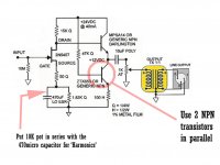
Here we have my go at the V12R with tracking CCS built for 10VDC out.
I reduced R4 R5 to 800 ohm so to have 5mA there (on the ccs)
R6 goes down from 10k to 1k8 so I have 3.2mA under the mosfet driving buffer.
Are these good choices ?
I reduced R4 R5 to 800 ohm so to have 5mA there (on the ccs)
R6 goes down from 10k to 1k8 so I have 3.2mA under the mosfet driving buffer.
Are these good choices ?
Attachments
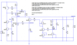
Depends on Vin-Vout available and on R15 value. Its a trial thing for some certain set-up. I would use the JFET CCS tail at such low rail voltage though. Has no start up condition glitch to solve. If not having the high Vgs (OFF) Q3 cascoding part handy, OK use BJT tail and tune the Zener kickstarter.Too much current in the zener (2.8mA) after startup
Can it work with a 12v zener for 10 vout ?
Admittedly it takes an effort.
")

LTspice simulations showed almost no significant difference in the css impedance with or without the startup resistors. I am not quite sure about the real world measurements since I usually use a DMM and my ears only 
I haven't tried V1.2 so far. I am using V1.1 (BiB) but with modified current source in my XMOS/AD1865 DAC (codenamed Moby Dick).
I haven't tried V1.2 so far. I am using V1.1 (BiB) but with modified current source in my XMOS/AD1865 DAC (codenamed Moby Dick).
Attachments
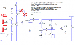
Ring of two BJTs is not a bad choice (I see your goal about not sparing Toshibas) but prefer IRF9610 for Q1 at this current level. For Q8 its the IRF9530 that remains best. You don't need the IRF9530 power for Q1 though and its slower. Lower parasitic capacitance Q1 part gives sense of silkier extended highs. I had used many combinations so I know but it just maybe proves not so noticeable on every different nature of client circuits it powers.
*You simulated with and without R4 just the modified BIB or the actual 1.2R with and without 2X330K? They both have so much PSRR in simulation that will make no interesting difference anyhow.
*You simulated with and without R4 just the modified BIB or the actual 1.2R with and without 2X330K? They both have so much PSRR in simulation that will make no interesting difference anyhow.
Here we have my go at the V12R with tracking CCS built for 10VDC out.
I reduced R4 R5 to 800 ohm so to have 5mA there (on the ccs)
R6 goes down from 10k to 1k8 so I have 3.2mA under the mosfet driving buffer.
Are these good choices ?
I have lost count of the number of times I have recommended that the CCS part alone be assembled and tested before a Builder adds on the shunt part of the regulator.D3 is a 10v zener... not sure if it will work... maybe I should use a 6v zener ?
Did you do that?
If not then disable everything to the right of R6 and disable M2 (pull out the drain lead).
Test the CCS without a load.
Then add on a 100r load and test again.
Then add on a second 100r and test again.
Post your results.
Salas, thank you for your advise! I know IRF9610's are better for the CSS and I do use them in most of my implementations. It is just that IRF9530 is four times cheaper and readily available...
Its probably because they use it in car audio amplifiers so more produced and spread
*You simulated with and without R4 just the modified BIB or the actual 1.2R with and without 2X330K? They both have so much PSRR in simulation that will make no interesting difference anyhow.
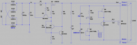
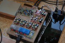
I simulated many different combinations. My first implementation of the BiB was with the CSS Ricardo is trying to improve. Here is a picture of an old implementation of mine and the two 220k SMD resistors I added to fix the startup issues:
PS: Why it takes like 10-15 minutes to actually see my post here?
Attachments
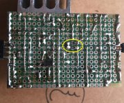
Because you have very few posts the system still puts you in the pipeline of approval. Its a software thing to avoid spam posters. Robots or human.I simulated many different combinations. My first implementation of the BiB was with the CSS Ricardo is trying to improve. Here is a picture of an old implementation of mine and the two 220k SMD resistors I added to fix the startup issues:
PS: Why it takes like 10-15 minutes to actually see my post here?
- Home
- Amplifiers
- Power Supplies
- SSLV1.1 builds & fairy tales