Salas, I was referred to by by TeaBag. In stead of buying a turbo supply from oracle audio, which is basically an unregulated supply with a shunt, using a salas lv.
The papst motor requires 240 mA during transient, or startup, and 45mA steady state. There is a small pcb in the TT which includes an LM317 a transistor, a couple of diodes and a realy for power on/off. The regulator is set for 24 V. The outboard supply needs to be about 27 V.
Has anyone used your circuit as a pre regulator for such a use before? Is it feasible?
Thanks, CC
Are you sure Oracle uses a Salas LV for their Delphi TT Turbo PSU? Did you examine it or you have some positive info? Having a link where they maybe state that?
P.S. They have used it before as pre-reg to many Buffalo DAC. Many examples in this very thread. It could be feasible in other apps too.
P.S. They have used it before as pre-reg to many Buffalo DAC. Many examples in this very thread. It could be feasible in other apps too.
" ticknpop
diyAudio Member
Join Date: May 2005
Location: toronto
The original MK 3 power supply was an oversized wall wart with a simple bridge rectifier and small capacitor.
The Turbo supply is an emi cap filtered input torrid power transformer with a double RC filtered output feeding a Zener based (Shunt?) Fet regulator - rather overpriced for what it is"
I don't think it's a salas, but I don't want to pay a grand and I already have their poor mans psu which comes in the same box. If it's feasible, I will order the 1.6 mm pcb from TeaBag
Here is another quote from ticknpop:
The newer Turbo 27 VDC power supply is an AC input EMI filter feeding one of the blue Indian low cost torroids from Digikey. a regular 4 pin bridge rectifier feeding 2 stage RC filter then an IR fet with a zener to it's base set up as what looks to be a shunt regulator. As a $1,000 upgrade it's a little short on value. You could easily DIY it better for $100 - $150. with FAST/SOFT recovery diodes, a C core or dual bobbin transformer, 105C caps etc..
The newer Turbo 27 VDC power supply is an AC input EMI filter feeding one of the blue Indian low cost torroids from Digikey. a regular 4 pin bridge rectifier feeding 2 stage RC filter then an IR fet with a zener to it's base set up as what looks to be a shunt regulator. As a $1,000 upgrade it's a little short on value. You could easily DIY it better for $100 - $150. with FAST/SOFT recovery diodes, a C core or dual bobbin transformer, 105C caps etc..
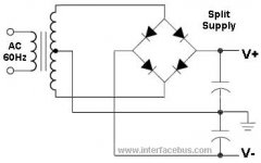
For a centre tapped transformer you must use a single bridge rectifier feeding the series connected smoothing capacitors.
This MUST feed into a pair of complementary regulators, i.e. one +ve and one -ve.
For a dual secondary you have options:
a.)
Convert to centre tapped and follow the above.
b.)
fit a single bridge rectifier on one winding feeding a single smoothing cap and feed that into a +ve regulator.
c.)
fit a single bridge rectifier on one winding feeding a single smoothing cap and feed that into a -ve regulator.
d.)
use both b and c to create a pair of complementary supplies.
e.)
use b twice over to create a pair of +ve supplies and series connect for a dual polarity.
f.)
use c twice over to create a pair of -ve supplies and series connect for a dual polarity.
Thanks Andrew,
I have a 20-0-20 center tap transformer
I connected one feed to a half bridge rectifier on the +ve (100 board)
I connected other feed to a half bridge rectifier on the -ve (200 board)
I connected the center tap to the series connected smoothing caps directly
I think I need a diagram to be sure. I'll try to post pic later when I get a chance
Last edited:
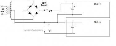
Necplusultra: I built what you are trying to do a while ago. That is, a balanced supply from a center-tapped transformer and a pair of sslv boards. I built a raw supply essentially as shown by 2channel above and fed DC to the Salas boards. In that case you don’t need the rectifiers on the boards. Find a convenient place to solder the DC-in wire, or install jumpers. I chose to use low value resistors in series to make a CRC filter, and kept the big electrolytics on the boards. Since I was making a phono preamp it was convenient to put the raw supply in a separate chassis, but of course not necessary. You can find photos of it in this thread about a year ago.
Like Nezbleu says. If you still want to use the standard input terminals on the Salas boards you need to remove the 'on board' rectifiers diodes and link through to the caps. ALternatively you could solder wires directly to the caps.
The effective connections are shown below. The bridge is 'off board" and the caps are the ones on the Salas boards.
The effective connections are shown below. The bridge is 'off board" and the caps are the ones on the Salas boards.
Attachments
- Home
- Amplifiers
- Power Supplies
- SSLV1.1 builds & fairy tales