Still almost there
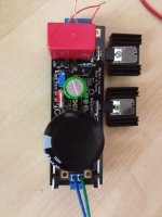
After many delays, this project advances. For no particular reason I wanted to balance the +/- CCS currents. To do this I ended up with CCS resistors of 5R||15R on the positive rail, and 5R||8R2||15R on the negative rail, which looks insane, but got me about 280mA per rail (as I recall).
This is to power an opamp-based phono board, I thought I had everything measured, but bought an enclosure that is barely big enough. In fact I filed away about a mm of the phono circuit board to cram it in. Plus the enclosure has ridges on the inside bottom (and top) which interfered with the mosfets, so I used a rotary (Dremel-like) tool to grind away some of the ridge to make things fit. It fits better than it looks.
Here are some photos.

You can see the ridge on the bottom I had to grind away.

The nasty looking bottom and the paralleled positive rail CCS resistors. At 10W each they should never get warm.

Here are the stacked 10W resistors on the negative rail.

You can see it's a tight fit!

I had to offset the boards vertically so I could overlap them horizontally, which made fitting connectors on the end panel a little more challenging.

The overlap may be a little clearer. Incidentally, I left the MOSFET leads untrimmed in case I needed to adjust the board height. Now that everything fits (barely) I will trim them short. The electrolytic caps are just making contact with the inside of the top cover, so I may grind away parts of the ridges there as well, to provide better air circulation. I'm thinking I may also add a dab of hot glue between those caps to hold them steadier.
Now to wire it all up!
After many delays, this project advances. For no particular reason I wanted to balance the +/- CCS currents. To do this I ended up with CCS resistors of 5R||15R on the positive rail, and 5R||8R2||15R on the negative rail, which looks insane, but got me about 280mA per rail (as I recall).
This is to power an opamp-based phono board, I thought I had everything measured, but bought an enclosure that is barely big enough. In fact I filed away about a mm of the phono circuit board to cram it in. Plus the enclosure has ridges on the inside bottom (and top) which interfered with the mosfets, so I used a rotary (Dremel-like) tool to grind away some of the ridge to make things fit. It fits better than it looks.
Here are some photos.
You can see the ridge on the bottom I had to grind away.
The nasty looking bottom and the paralleled positive rail CCS resistors. At 10W each they should never get warm.
Here are the stacked 10W resistors on the negative rail.
You can see it's a tight fit!
I had to offset the boards vertically so I could overlap them horizontally, which made fitting connectors on the end panel a little more challenging.
The overlap may be a little clearer. Incidentally, I left the MOSFET leads untrimmed in case I needed to adjust the board height. Now that everything fits (barely) I will trim them short. The electrolytic caps are just making contact with the inside of the top cover, so I may grind away parts of the ridges there as well, to provide better air circulation. I'm thinking I may also add a dab of hot glue between those caps to hold them steadier.
Now to wire it all up!
Hi, do you need isolators between the mosfets and heatsinks?
YES
Having a build issue
Hey All,
I'm trying to get a 15V SSL1.1 board going but not having much luck. The LEDs don't light up, and I'm only measuring 1.6V or so at the outputs when I apply power. Not sure what's going on. I rechecked that I got all the parts in the right place, but I'm pretty much a noob, so any help would be great.
I chose the parts based on the excel calculator:
R103: 2K
R105: 1K trimmer (set to 750)
D101: jumpered
Thanks,
Attachments
Last edited:
I didn't realize the unpopulated LEDs needed to be jumpered.
What resistor value should I select for the dummy load? I'm looking to simulate 90ma, am not quite making sense of the calculation.
I end up with 1.3k, but that seems way too high compared others. I think 30something Ohm seems more appropriate?
I'll try that tonight. Thanks!
What resistor value should I select for the dummy load? I'm looking to simulate 90ma, am not quite making sense of the calculation.
I end up with 1.3k, but that seems way too high compared others. I think 30something Ohm seems more appropriate?
I'll try that tonight. Thanks!
Looks like one of the LED's in the D10X string is open.
There are 4 LED's, if you only use 3 (I see 3 green's), you need to jumper the 4th one.
Also, make sure you have a load in the output when you fire up the reg. Don't leave it open as in the pic.
Good luck,
Thanks!
15V / 0.09A = 166.67
Use (2 x 330 ohm 2W) or (3 x 500 ohm 1 W) resistors in parallel will do.
Unable to up the output voltage
Using FETs, no BJT's, except for the BC550 in position Q104.
My target voltage is 5.3V, with a load current of 450mA. I'm using a dummy load of 11.6 ohms:
5.3 / 11.6 = 457mA
I am using 4 green LED's, along with a 5.6 ohm current shunt resistor, in order to get the required current.
2.07 x4 = 8.28; 8.28-5.1/5.6 = 570mA
However, I am unable to get any higher voltage than 5.3V. Using a 2K pot, 2 red leds in the adjustment chain, with a 220r resistor.
Any suggestions?
Thanks for your help...
What is the actual voltage drop across the CCS setting resistor? Does it confirm 570mA for Vdrop/Rccs, Is the pot changing for Ohm or its stuck?
Hi Salas,
Thought about it and change the R(limit) from a 5.6 to a 4.7, it now works. Drop across R(limit) is 2.51, providing total current of 530mA, with approx 80mA shunt. Should run nicely.
Thanks for your assistance, as always, you are a gentleman and a (Greek) scholar!
Hi Salas,
Thought about it and change the R(limit) from a 5.6 to a 4.7, it now works. Drop across R(limit) is 2.51, providing total current of 530mA, with approx 80mA shunt. Should run nicely.
Thanks for your assistance, as always, you are a gentleman and a (Greek) scholar!
Salas,
Still a bit curious as to why the math doesn't work out here: I measured the exact drop across the green LED's (2.07V each)
Now the drop across the 4.7R is 2.51V
(2.07 x4) = 8.28; 8.28-2.51 = 5.77V
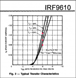
The curve indicates for Vgs at 5.7V with Ta=25C to be about 1A. (Clearly; more to the numbers that this calculation?)
It's interesting to note the spreadsheet indicates a total current of 650mA output using a 4.7R resistor, for 5.3V and 450mA load.
All circuit parts as recommended.
Can you provide some insight? How to account for this difference? I can understand variations of perhaps 10% due to parts, but it seems a bit much in this case.
Thanks.
Last edited:
Salas,
Still a bit curious as to why the math doesn't work out here: I measured the exact drop across the green LED's (2.07V each)
Now the drop across the 4.7R is 2.51V
(2.07 x4) = 8.28; 8.28-2.51 = 5.77V
The curve indicates for Vgs at 5.7V with Ta=25C to be about 1A. (Clearly; more to the numbers that this calculation?)
It's interesting to note the spreadsheet indicates a total current of 650mA output using a 4.7R resistor, for 5.3V and 450mA load.
All circuit parts as recommended.
Can you provide some insight? How to account for this difference? I can understand variations of perhaps 10% due to parts, but it seems a bit much in this case.
Thanks.
If you could curve trace that individual MOSFET taking into account the VDS (equals vin-vout in this case) to test at, and the junction temperature Tj in your particular set up, it would surely show the deviation parameters that make sense.
Making the basic VRset/Rset verification first when assembly is over with a light load resistor, shows the truth without all the above.
Tj in particular can play a big part when targeting over 400mA for an IRF9610. Beyond batch deviations etc. See how it can vary for 0.6A between extreme temp cases at -6V VGS as an example.
Attachments
- Home
- Amplifiers
- Power Supplies
- SSLV1.1 builds & fairy tales