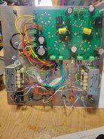
Just finished another SSE built. Got some question about biasing. I used Hammond 374BX and EL34 tubes. While using 5AR4 rectifier tube, I measured B+ 428V, Plate 424V, Cathode 30V and I use a 560 Ohm bias resistor. This computes to 53 mA biasing current and (424 - 30) X 0.053 = 21 W dissipation.
Shall I drop the resistor to 450 Ohm or so to bring the current up to 66 mA like what George specified in his design?
Shall I drop the resistor to 450 Ohm or so to bring the current up to 66 mA like what George specified in his design?
Attachments
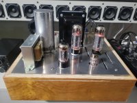
That is a very compact and efficient use of the square baseplate! I am considering a similar approach for a new home for a SPP, so it was good to see your version.
What is that row of speakers for, at the back of the picture?
If you tack a 2.2K resistor across the 560R one, that will be equivalent to close to 450R. It only dissipates half a watt, so a 2W will be plenty. Then you can see if the extra burden on the tubes pays off.
What is that row of speakers for, at the back of the picture?
If you tack a 2.2K resistor across the 560R one, that will be equivalent to close to 450R. It only dissipates half a watt, so a 2W will be plenty. Then you can see if the extra burden on the tubes pays off.
Thanks for the suggestion. I wonder why my cathode voltage is lower 31 vs. 37 on George's design page using similar power supply and tubes which requires a drop in the bias resistor to get the desired current ? Even if I switch to solid state rectification, the cathode voltage is not much higher: 33 V. The row of speakers in the background is my center channel speaker containing 16 X 2.5 inch fullranges. The aluminum base plate 12X12 inch and as you can see space is tight. I had contemplated upgrading the OPT to the Edcor CXSE25-5K, but the added weight and space requirement cause me to pause and think for a while. With the current weight, it is quite and exercise to lift the base plate up and gently replacing it back on the wood base
Well I replaced the 560R bias resistor with a 430R and the Cathode Voltage drops ! B+ is now at 403 instead of 430, Plate at 397 instead of 425 and Cathode at 26 V instead of 31V, this is with tube rectification. The bias current is now 26/430 = 60mA and dissipation 22W same dissipation as when the resistor was 560R. It looks like something is restricting the power dissipation from going higher than 22W. Anybody has any idea what could cause that ? The tube rectifier is 5AR4, is it too weak to pump out additional current which cause the cathode voltage to sag? I switched over to SS rectifier and the situation is not much better, B+ still drops compared to 560R bias resistor. with 430R, B+ is now 424 vs 450 when it was with 560R. Plate is 417 vs 446 and Cathode is 28 vs 33 when 560R was used. This results in dissipation about 25W vs 24W when 560R was used with SS rectification. So even with SS rectification, something is still trying to limit dissipation. I welcome any explanation
So I went back and look at TubeLab SSE design page where it list power output simulations for different type of tubes, and I notice that when the bias resistor drops in value, the Plate voltage and Cathode voltage drops also. So that is consistent to what I am seeing with my 6L6 SSE amp. However in the simulation there is also an increase in bias current that would more than offset the drops in the voltage such that the net power dissipation is larger than before. In my amp there is an increase in current, but not as large which result in the power dissipation remaining pretty much the same as before. This is what I would like to understand why that is the case. Incidently when I replaced the NOS Mullard 12AT7 with a Golden Lion 12AT7, there is a slight bump in the voltages and the power dissipation goes up by 1 watt. It seems that the Cathode bias voltage of the power tube is dependent on a lot of things, including the brand of preamp tube used.
I use Hammond 374BX which is rated at 750VCT and 200mA. So I did not think it was the bottleneck. I had thought that may be the Sovtek 5AR4 rectifier tube I used is weak at providing voltage/current. But then I switched to SS rectifier the result is just marginally better, with 560R, current is 58mA and dissipation is 24W vs 69mA and 28 W in George's simulation table, so that's why I did not think the rectifier tube is the bottleneck. At this point I am ready to swap it out with another rectifier tube just to see if it makes any difference.
I've built a few SSEs and like OldHector says found the power transformer to be the bottleneck. Between tube & SS rectifier, I find SS to always provide additional 25-30v.
When using SS, I remove the GZ34 so the heater is not loading the transformer (gets really hot too). This seems to be the best way for me to get good output.
When using SS, I remove the GZ34 so the heater is not loading the transformer (gets really hot too). This seems to be the best way for me to get good output.
- Home
- More Vendors...
- Tubelab
- SSE finished, some questions