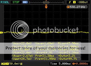
Well I take new measurements with my scope and the sinus signal is greatly attenuated, nearly invisible at 50mV scale, and the hum as greatly decreased, I have to put my ear right next to the speaker to hear it.
However, r17/r27 are still running quite hot, but no fume.
B+ = 448V DC
VK = 41Vdc
Diss = 29.79w 41/560*(448-41)
If my calculation are good, there's 73mA running through r17/27, so they dissipate something like 3W, right?
However, r17/r27 are still running quite hot, but no fume.
B+ = 448V DC
VK = 41Vdc
Diss = 29.79w 41/560*(448-41)
If my calculation are good, there's 73mA running through r17/27, so they dissipate something like 3W, right?
Last edited:
However, r17/r27 are still running quite hot, but no fume.
I had a similar problem with a 680 ohms 5 watt Yageo cement resistor. The resistor was scorched to the point where all the writing on was burnt off.
I installed 7 watt resistors and it has been fine ever since.
If the hum is now very faint that is a good improvement although there shouldn't be any.
I don't think the resistor selector switch is the cause of the hum, disconnecting it was just to revert the amp to its
basic config in order to pinpoint the source of the hum.
Try to get a higher wattage cathode resistor, if it is large you will have to twist the leads to fit it in place.
basic config in order to pinpoint the source of the hum.
Try to get a higher wattage cathode resistor, if it is large you will have to twist the leads to fit it in place.
I found some mills MRA12, 12 Watts witch has a small body,i think they should do the trick, for now I'm using a 680R 5W with a 3K3 2W in parallel (witch makes 558R 7W)
I want to measure the RK temp as well as the CL60 witch is in series with the PWr trafo primary (it runs quite hot too)
I want to measure the RK temp as well as the CL60 witch is in series with the PWr trafo primary (it runs quite hot too)
I've never measured the temperature of my cathode resistors so I can't say if 110C is too hot. I've touched them several
seconds after power off and they do feel very hot.
After a few hours of playing my power xfrmr (Edcor XPWR035) gets very warm not hot, I can hold it for more than
15 seconds without discomfort.
Oh, maybe you were probably referring to the CL60 as being very hot, not your power xfrmr. I use a CL90 but I've
never touched it to feel the temperature.
Last edited:
Yes I was talking about the CTN, and it's a CL90 (I made a typo), the Pwr trafo is very warm after hours of use (It's a hammond and they are known to get warmer than Edcors).
Seems like 110 is fine as according to calculation, the res are dissipating 3W.
I need to retry the amp for audible hum, as from the scope measurements I can't see the sinus waveform anymore (on 50mV scale)
If no hum or really faint hum, I'll try UL/CFB.
Seems like 110 is fine as according to calculation, the res are dissipating 3W.
I need to retry the amp for audible hum, as from the scope measurements I can't see the sinus waveform anymore (on 50mV scale)
If no hum or really faint hum, I'll try UL/CFB.
Hot Stuff....
With an ICL, as it's temp rises, it's resistance decreases... hence the slowing of current as power is applied. The CL-90 has an upper operating range of around +175 C, so 110 is not too hot. I use these on every build and rebuild/repair, making sure there is plenty of open space around them...
With an ICL, as it's temp rises, it's resistance decreases... hence the slowing of current as power is applied. The CL-90 has an upper operating range of around +175 C, so 110 is not too hot. I use these on every build and rebuild/repair, making sure there is plenty of open space around them...
denny3249 : Thanks, I also took a look at the cl90 datasheet and was reassured ")
I made new scope measurements in triode and UL+cfb, here they are:

Triode Mode
UL + CFB
Big improvement from the first measurements
Listening impression confirm that improvement, now the hum level in Ul + CFB is the same as the one of the triode mode before.
The scope measurements and listening session where made with the ul/triode and CFB switches in place, choke and supplemental cap.
What I've done was to remove the RK selector, installing 560R RK on terminal post soldered on pcb (for ease of replacement) and shortening all my wirings (picture to come). The inner layout is far cleaner than before with shorter wires.
However, I still have some hum, don't know where it comes from and my RK and cl90 are smelling hot (they don't before) maybe because heat is burning finger oils...
I made new scope measurements in triode and UL+cfb, here they are:

Triode Mode

UL + CFB
Big improvement from the first measurements
Listening impression confirm that improvement, now the hum level in Ul + CFB is the same as the one of the triode mode before.
The scope measurements and listening session where made with the ul/triode and CFB switches in place, choke and supplemental cap.
What I've done was to remove the RK selector, installing 560R RK on terminal post soldered on pcb (for ease of replacement) and shortening all my wirings (picture to come). The inner layout is far cleaner than before with shorter wires.
However, I still have some hum, don't know where it comes from and my RK and cl90 are smelling hot (they don't before) maybe because heat is burning finger oils...
So, the amp is running for two hours now and all is fine, the burnt smell progressively disappeared witch confirm my suspicion about finger oil being burned by the res and tubes (I forgot to clean the tubes) .
I ordered 560r Mills resistors for RK and also a pair of Auricap XO 0.22 600V for coupling caps (wanted to try them as they receive quite a lot of fame from their users)
Still have to find out why I get the hum (even if it has greatly reduced) and if it's possible to lower it further.
I ordered 560r Mills resistors for RK and also a pair of Auricap XO 0.22 600V for coupling caps (wanted to try them as they receive quite a lot of fame from their users)
Still have to find out why I get the hum (even if it has greatly reduced) and if it's possible to lower it further.
Now that you've installed terminal posts for your R17, R27 you should reconnect your resistor selector switch and see what happens.
HOWEVER, if you're currently using two parallel for R17 and R27 it wouldn't work, there should only be a single resistor on the board in
combination with the selector switch so wait until you get your new resistors.
I have a feeling that when you install the higher wattage resistors the hum might be eliminated. You've already double checked your wiring,
you're using shielded input wire and your power and OPT's are correctly oriented. So it's hard to see what else could be the problem.
That's right, I only ordered 560R ones because I will work with a fixed cathode for some times, the goal being to eliminate the remaining hum.
I installed shielded input wires (Sommercable Isopod) but the hum seems a little louder now (in UL/cfb)....
I'll buy some budget 10W cathode resistor to see if higher wattage do something. And maybe the new coupling caps (Auricap XO) will do something too.
I installed shielded input wires (Sommercable Isopod) but the hum seems a little louder now (in UL/cfb)....
I'll buy some budget 10W cathode resistor to see if higher wattage do something. And maybe the new coupling caps (Auricap XO) will do something too.
I installed shielded input wires (Sommercable Isopod) but the hum seems a little louder now (in UL/cfb)....
Okay, try grounding your board a different way. You now have your board grounded via a connection from one of your
RCA grounds to your star ground. - Remove that ground connection.
There are five input terminal slots on the board and the middle one is free, it is also on the ground plane of the board.
Ground your board by connecting this terminal slot to your star ground.
I made the change you suggested to board grounding without significant changes.....
I tried using a filtered IEC inlet, no changes.
I tried using the amp without the 12at7, no changes, so it's not from the input stage.
I tried with 12at7 on and without output tubes = no hum, so it's on the output stage.
I tried using a filtered IEC inlet, no changes.
I tried using the amp without the 12at7, no changes, so it's not from the input stage.
I tried with 12at7 on and without output tubes = no hum, so it's on the output stage.
I installed shielded input wires (Sommercable Isopod) but the hum seems a little louder now (in UL/cfb)....
When you mentioned that the hum got louder when you installed shielded input wire I was thinking that somehow
there was a problem with with grounding the pcb via one of the RCA grounds. But the hum persists with the alternative
pcb grounding I suggested.
So, now it's hard to see what else could be the problem. You've verified that your transformers and choke are all properly
oriented. You've also double checked your basic triode wiring config. Your speaker and RCA jacks are all properly isolated
from the chassis plate. Your pcb has only one ground connection and all is grounded via your star ground point.
When you get your new cathode resistor it may or may not help when you install it, if not then it's hard to know what else to suggest.
Maybe you can post a photo showing your transformers and choke orientation.
- Status
- This old topic is closed. If you want to reopen this topic, contact a moderator using the "Report Post" button.
- Home
- More Vendors...
- Tubelab
- SSE 100Hz Hum headache