F2D Variant....
Here's the as promised F2D variant.... An R085 will drop right in with the appropriate source resistor. It takes about 30 minutes for the operating point to settle, but that may be because the IRFP9240 & the IXTH6N50D2 are a long thermal distance apart on my heat sinks.... A thermistor on the IXTH6N50D2 wired between the wiper of the pot and the source of the IRFP9240 might help here, I'll have to give that a try....
Roscoe
Care to share your schematic?
Here's the as promised F2D variant.... An R085 will drop right in with the appropriate source resistor. It takes about 30 minutes for the operating point to settle, but that may be because the IRFP9240 & the IXTH6N50D2 are a long thermal distance apart on my heat sinks.... A thermistor on the IXTH6N50D2 wired between the wiper of the pot and the source of the IRFP9240 might help here, I'll have to give that a try....
Roscoe
An externally hosted image should be here but it was not working when we last tested it.
wrenchone, careful selection of the time constant in the RC network feeding the base/gate of the cap multiplier/VR pass transistor should give both a nice slow turn-on so you don't get a turn-on thump, and a nice low current initial charge of the multiplier/VR's output caps...
Roscoe
Roscoe
I was thinking about biamping and only using this or the delite for 500hz up
with a 8 ohm driver. Will I still need a large output cap or can I get away
with something a lot smaller. If this was a voltage amp I could even pick
a small output cap and use it as the crossover but this is a current source
amp so the rules are a lot different but I still wonder if I could use a much
smaller output cap,
Time to beat a dead horse
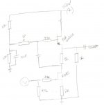
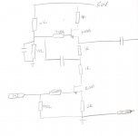
I have some down time for a couple of days and besides doing a little camping, I want to pull together this schematic and need some help determining values. I am largely basing what I have so far on Pass articles and in no way claim they are even realistic. I think i have most of it and have only a few questions. The three resistors that I am most unsure of include the one marked with a question mark, as well as the Rl of the lower fet and Rs of the upper fet, which I have currently parallel to Rl. I have chosen 1R for Rl of the lower fet as I believe this will give a gain of about 13, but I am not sure as I believe it is there simply to pass the signal to the SF which acts as an active load. I am asumming the active load presents a very high impedance and should max out the gain of the lower fet, which i believe is about 13. I am unsure about the Rs of the upper fet and whether I have it layed out properly or it should be added in line with Rl. It seems thta, as is, it would allow for a larger value vs putting it in series with Rl. I am afraid that this may affect the output impedance in a negative way. NOt sure how to look at it. The resistor with a question mark should be a high value, I think, like 10K, but once again unsure of how this affects things. IT would appear to be a load to the lower fet and a higher value is good. THanks and no laughing!
I have some down time for a couple of days and besides doing a little camping, I want to pull together this schematic and need some help determining values. I am largely basing what I have so far on Pass articles and in no way claim they are even realistic. I think i have most of it and have only a few questions. The three resistors that I am most unsure of include the one marked with a question mark, as well as the Rl of the lower fet and Rs of the upper fet, which I have currently parallel to Rl. I have chosen 1R for Rl of the lower fet as I believe this will give a gain of about 13, but I am not sure as I believe it is there simply to pass the signal to the SF which acts as an active load. I am asumming the active load presents a very high impedance and should max out the gain of the lower fet, which i believe is about 13. I am unsure about the Rs of the upper fet and whether I have it layed out properly or it should be added in line with Rl. It seems thta, as is, it would allow for a larger value vs putting it in series with Rl. I am afraid that this may affect the output impedance in a negative way. NOt sure how to look at it. The resistor with a question mark should be a high value, I think, like 10K, but once again unsure of how this affects things. IT would appear to be a load to the lower fet and a higher value is good. THanks and no laughing!
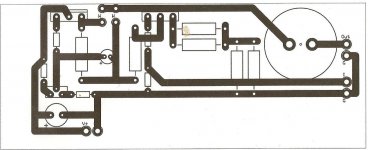
Attachments
I think there's some potential in all these devices, and unfotunately, while
I've had time to run up some quick curves and listen to a few examples,
the time isn't there to do extensive listening with every permutation. This
is unfortunate because, as I said: Occasionally there is a surprise.
Here's a curve of an R085 running at 2 amps with a mu follower and 2 ohms
of degeneration (providing degeneration and a bias drop for direct coupled
input).

This is what I am basingmy experiments on. Direct coupled means no negative gate bias, correct? Seems to beat the performance of L'Amp with CCS. I think i can delete the 4R and add a couple pots across the bigger Rs and have a functioning circuit. I think the cap needs to parallel both divider resistors. Just checking to see if I had missed something or calculated something wrong.
Last edited:
I just read it before you posted. Here is what I am thinking, I know you must get tired of helping me. I do appreciate it. The lower fet is biased in what i think is a reasonable way. Based on what i have read and heard from Nelson, the R085 would yield about 2A with 2R of degeneration and gate grounded. This would allow the dropping of an input cap. The difiiculty comes in the CS. IS it SRPP or is it MU, dunno. The 2R of power resistros beneath the upper fet should set its current at similar or same level as lower fet. I know this is dependent on Vdivider and this is where I have to do some math. I think I actually need somewhere about 16-18V at the gate. By pulling signal from above lower 1R resistor, The gain should be about 13-15. I could be wrong here, as I am unsure of the effect of the top fet, and maybe even the formula for doing so. I guess I will build with lightbulb tester and fire up and see if it explodes.

- Status
- This old topic is closed. If you want to reopen this topic, contact a moderator using the "Report Post" button.
- Home
- Amplifiers
- Pass Labs
- SS 120R085 Depletion Mode Jfet