Hi,
My copy of the book got lost in one of many moves, sorry.
Allen used this in one of his early "real time" preamplifiers.
Yes, unity gain would be from one the two lines of the balanced signal. If you look at the balanced signal the gain is indeed 0.5, or close to 0.5 but a touch lower. I guess I'm living too much in SE land...")
Ask Allen.
Ciao T
Alas, I don't have Allen's book, but thanks for letting me know! (You wouldn't be willing to copy the relevant page for me, would you? Perhaps if we ask Allen first?)
My copy of the book got lost in one of many moves, sorry.
Allen used this in one of his early "real time" preamplifiers.
However, I take issue with the name "Unitiy Gain Balanced to Single-ended Converter." because it is not unity gain! It has a gain of one half.
Yes, unity gain would be from one the two lines of the balanced signal. If you look at the balanced signal the gain is indeed 0.5, or close to 0.5 but a touch lower. I guess I'm living too much in SE land...
Incidentally, why call it 'super linear' rather than ultralinear, as it used to be called? e.g., P. Read (1960) Ultralinear Cathode Follower. RSI, September, pp979-82.
Ask Allen.
Ciao T
Sy,
Surely Sir, you jest?
Set up correctly an SRPP stage has lower distortion than ANY other form (including Mu-Follower or CCS load) of Gainstage (not follower) that can be realised using the same double triode.
Of course, not all SRPP's are set up correctly for low distortion.
Ciao T
Reading in Morgan Jones book about tube amplifiers, this statement seems to point in the others direction than his results?
As I remember, a mu-follower is somewhat better than a SRPP. But perhaps this optimized SRPP is another circuit than Jones was using?
Do you have any information about this optimization?
Surely you jest? This circuit was documented as one of the 'dead end's" from the 1980 in Allen Wrights TPCB (Tube Preamp Cook Book). He presented it as "Unitiy Gain Balanced to Single-ended Converter.
Hey Buddy,
i don't ever remember writing this (although it sounds like me) so I just scanned through my TubePreamp CookBook again, and can find ZERO reference to this. can you enlighten me, or have you attributed something someone else said to me?
Regards, Allen
Alas, I don't have Allen's book, but thanks for letting me know! (You wouldn't be willing to copy the relevant page for me, would you? Perhaps if we ask Allen first?)
However, I take issue with the name "Unitiy Gain Balanced to Single-ended Converter." because it is not unity gain! It has a gain of one half.
I would NOT approve of anyone copying parts (or all) of my book - don't be so tight and just buy one. Theres a lot of GOOD stuff in there.
And as you can see in my post to TL above, I never wrote what he attributed to me.
Regards, Allen
Allen,
You probably forgot more about making tube preamps than most of us ever will know.
Many years ago you gave me an early copy of your Book (first printing).
As I have a near eidetic memory that seems quite reliable over many years I remember this book containing a (hand-drawn) schematic of the very first "Real Time Preamp". In the accompanying text you where bellyaching how you had a nice balanced preamp but the HiFi world in Oz was single ended, so you had to include a Balanced to SE Converter on the end of the preamp.
This consisted of a Cathode Follower with triode below that was wrapped in an NFB loop to produce the correct inverting gain, or to wit, what John Broskie now calls the "Broskie Follower".
I am unsure if you removed this section from later revisions in your book.
Of course, it is POSSIBLE that I have gotten memory engram's mixed up and this was some-one else schematic, but I am quite positive.
Ciao T
Hey Buddy,
i don't ever remember writing this (although it sounds like me) so I just scanned through my TubePreamp CookBook again, and can find ZERO reference to this. can you enlighten me
You probably forgot more about making tube preamps than most of us ever will know.
Many years ago you gave me an early copy of your Book (first printing).
As I have a near eidetic memory that seems quite reliable over many years I remember this book containing a (hand-drawn) schematic of the very first "Real Time Preamp". In the accompanying text you where bellyaching how you had a nice balanced preamp but the HiFi world in Oz was single ended, so you had to include a Balanced to SE Converter on the end of the preamp.
This consisted of a Cathode Follower with triode below that was wrapped in an NFB loop to produce the correct inverting gain, or to wit, what John Broskie now calls the "Broskie Follower".
I am unsure if you removed this section from later revisions in your book.
Of course, it is POSSIBLE that I have gotten memory engram's mixed up and this was some-one else schematic, but I am quite positive.
Ciao T
As I have a near eidetic memory that seems quite reliable over many years I remember this book containing a (hand-drawn) schematic of the very first "Real Time Preamp". In the accompanying text you where bellyaching how you had a nice balanced preamp but the HiFi world in Oz was single ended, so you had to include a Balanced to SE Converter on the end of the preamp.
This consisted of a Cathode Follower with triode below that was wrapped in an NFB loop to produce the correct inverting gain, or to wit, what John Broskie now calls the "Broskie Follower".
I am unsure if you removed this section from later revisions in your book.
Your memory is perfect! And that schematic is still there, I just didn't look in that section of the book when I said I didn't write it.
That circuit was replaced in later versions of the "Realtime" pre with full SLCFs, mostly because this one lost information because the upper Cf and lowe anode follower were never identical, and stuff got lost in the mix.
But whoever is saying it's gain is 1/2 has never measured it - I promise you the gain is identical to the CF = juat under 1, because to have it sound even half decent, you had to tweak the anode follower to match the CF's gain. Full story in the book.
Regards, Allen
Ah, it sounds like your version didn't have the potential divider at the input of the upper CF, like Broskie does? That would make yours unity gain.But whoever is saying it's gain is 1/2 has never measured it - I promise you the gain is identical to the CF = juat under 1, because to have it sound even half decent, you had to tweak the anode follower to match the CF's gain. Full story in the book.
Ah, it sounds like your version didn't have the potential divider at the input of the upper CF, like Broskie does? That would make yours unity gain.
Ihave no knowledge of what Brosksi does, and very little interest.
My circuit was designed in 1984 and published in the TubePreamp CookBook in1994. Full details, etc in the book.
regards, Allen
Hi,
Are we talking about this:
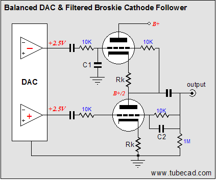
?
If so the gain for each "phase" of the balanced signal is approximatly unity, just like Allen's circuit. And, by your leave, there is no potential divider on the upper triode. The 10K resistor from the upper grid to the output is "bootstrapped" and appears as many times it's value (appx. resistor value / 1 - gain)...
Ciao T
Ah, it sounds like your version didn't have the potential divider at the input of the upper CF, like Broskie does? That would make yours unity gain.
Are we talking about this:
?
If so the gain for each "phase" of the balanced signal is approximatly unity, just like Allen's circuit. And, by your leave, there is no potential divider on the upper triode. The 10K resistor from the upper grid to the output is "bootstrapped" and appears as many times it's value (appx. resistor value / 1 - gain)...
Ciao T
If so the gain for each "phase" of the balanced signal is approximatly unity, just like Allen's circuit. And, by your leave, there is no potential divider on the upper triode. The 10K resistor from the upper grid to the output is "bootstrapped" and appears as many times it's value (appx. resistor value / 1 - gain)...
Exactly, but what a horribe nonconceptual way o drawing a schematic.
I have to twist myhead around to gain an dea of what it does.
And I can tell you, it's close enough to my idea to not sound good. I haven't used it since 1984.
regards, Allen
Tried both the AIkido and Gomes and I like the Gomes better.
But I also found that in all these SRPP-like-gain+SRPP-like-follower circuits there needs be be a bit of separation of B+ between the 2 stages otherwise they sound squeaky.
I ended up dropping the B+ (previously common to gain and follower) to the 1st stage by about 10V using a drop resistor and another layer of bypassing from there.
A lot more low level detail and the thinning + loss of depth that occurs with symphonic passages is reduced.
Hi all
I put a coin for the SRPP. Is more "Natural" and "Neutral" and hasn't a "Sound"
Cathode follower, due to high intinsic feedback, is a PIA
Only for drive complex load, however better than Source or Emiter follower
We can read a Mathematical explanation here
http://digilander.libero.it/paeng/cathode_follower_follows__audio.htm
Is more easy and comprenhensive than talk in therms like "Natural"...etc.
Cheers
I always thought the CCDA beat the push pull SRPP with regards to distortion at line level (.4V to 1V rms).
Ore's results always impressed me condsering that this include a fairly significant 2H from the passiv I/V on the TDA1541 and the noise floor is the dac as wel. It also shows that the CDDA like all CF's have lowest distortion into an specified load (based on rp of the tube).
bmp.jpg)
This is from his webpage (sorry don't no why this picture is so large), I've also noticed that Broskie seems to have moved to the CCDA over the mu stages. IME to get -90db 2H with CCDA you just need to tune it with the right load, (ie pot for the next stage, or resistors, or combo). And its usually around 5k-15k dpending on the tube. Obviously I;m not talking about a 20V output but a line stage. I think the CCDA may be tough to beat if you can deal with the coupling cap.
For 20V out whats wrong with a common cathode 6c45p led bias? I can find the link but with a CCS load I have seen -60db 2H at 15V output. Would seem to have a lower noise floor than the Impasse with its neon bias ?
Ore's results always impressed me condsering that this include a fairly significant 2H from the passiv I/V on the TDA1541 and the noise floor is the dac as wel. It also shows that the CDDA like all CF's have lowest distortion into an specified load (based on rp of the tube).
This is from his webpage (sorry don't no why this picture is so large), I've also noticed that Broskie seems to have moved to the CCDA over the mu stages. IME to get -90db 2H with CCDA you just need to tune it with the right load, (ie pot for the next stage, or resistors, or combo). And its usually around 5k-15k dpending on the tube. Obviously I;m not talking about a 20V output but a line stage. I think the CCDA may be tough to beat if you can deal with the coupling cap.
For 20V out whats wrong with a common cathode 6c45p led bias? I can find the link but with a CCS load I have seen -60db 2H at 15V output. Would seem to have a lower noise floor than the Impasse with its neon bias ?
Last edited:
The neon in the ImPasse is not used for bias, it's used for preventing arcing at turn-on. The bias is provided by LEDs, which are stunningly quiet. I use the same bias scheme on the input stage of my MC phono preamp, with the noise from the LED bias buried below the self-noise of the cartridge.
No, not really. The explanation given is misleading because it assumes a device with only square-law nonlinearity. Even an ideal valve is 3/2 power law, and a real valve will be even more complicated. All those nasty higher-order terms created by the feedback are actually already present before the feedback is applied. CF is fine provided it is correctly designed. Many audio CFs are badly designed. Of course, if you believe that feedback is bad then you must stick to using pentodes only in grounded cathode configuration.popilin said:We can read a Mathematical explanation here
Feedback is lyke an electronic perpetuum mobile, is condemned to fail.
Agreed. Particularly in the southern Hemisphere, where NFB becomes PFB and the electrons get all confused vacillating back & forth until they become disoriented
Agreed. Particularly in the southern Hemisphere, where NFB becomes PFB and the electrons get all confused vacillating back & forth until they become disoriented
I wonder how people compelled to repeat this as if it was a practical problem ever get their fingers to reach the keyboard - haven't they heard of Zeno's paradox?
a understanding of Calculus, circuit theory gives fine answers to how well feedback "works" - even in the presence of delay
for audio frequencies and gain devices with sub microsecond delays the answer is that feedback can work basically as well as we can measure down to the noise floor
- Status
- This old topic is closed. If you want to reopen this topic, contact a moderator using the "Report Post" button.
- Home
- Amplifiers
- Tubes / Valves
- SRPP vs. plate loaded, musicality and details