Hello Folks!
Am seeking advices for my trial and error built, single-ended EL 156. Have been dredging the NET for ideas from the generous guys, willing to share their knowledges. It was a gamble piecing together a circuitry with enough current to fully drive the EL 156, using the interesting SRPP #56 > D3A .
Can someone tell me what's the 6CG7 doing at the grid of EL 156?
I've tried out the 2 stage approach using C3M. Nice but not enough oooomph!
I'm used to the type of dynamics from my IPC 1026 theatre amp. Ofcource I'm not expecting that from a SE amp! Reason for embarking onto this project was to downgrade my system. Those heavy irons is too strainous for a retired 73 yrs old engineer.
Don't know how to simulate the power supply using PSUD! So, just follow what's normally done and blind to dc ripples and harmonic distortions.
Presently, the amp sounds good, stable, no hum and no pitchy high.
I strongly beleives that with the help from this community, it'll eventually evolved into a devine sounding machine.
Thanking All In Advance,
Zekk
Attachments
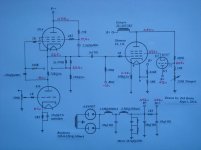
Your first stage is not an SRPP but a mu-follower.
The 6CG7 is not a voltage regulator, but provides a form of UL operation by returning a proportion of the anode voltage to g2. I'm curious: how did you design a circuit without knowing how it works?
I did'nt designed it! It was a cut & paste from various schematics. I'm just a copy-cat! There're a lot of simple Japanese design but I prefers exotic style
.Ya.. I'm confused and not understanding what's mu-follower, double mu-follower nor srpp!
Last edited:
The EL156 is silly easy to drive. A few years ago I built an EF86 -> EL156 UL amplifier with loop feedback. Still one of my favorite builds for ease of construction and the quality bass with the big Hammond output transformer.
My Italian friend told me that EL 156 is 4x more sensitive than a 300B. So, taking that into consideration, I choose a #76>D3A>EL 156 design. If that do drive a 300B, it'll over drive the EL 156 four times.... or is that wishful thinking!?
But no more(Alan Kimel) mu stage for drive it.
I would more emphasis on making direct coupling, for this lower voltage D3a plate in order that the cathode voltage thereof been at the same potential of the grid of the outlet valve.
Add a source of negative voltage to the cathode 56 in order to maintain the voltage in series Stage Mu.
I would more emphasis on making direct coupling, for this lower voltage D3a plate in order that the cathode voltage thereof been at the same potential of the grid of the outlet valve.
Add a source of negative voltage to the cathode 56 in order to maintain the voltage in series Stage Mu.
Last edited:
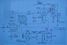
How about more simple ? And less problems with the heaters
Mona
What u meant by having less problems with heaters?
BTW, the #56 tube is heated by lithium battery to tame the humming.
The 6CG7 UL circuit as shown does not return the screen current (or typically 40% of it) to the output, like normal UL mode. (or the 100% for triode mode) So this will end up giving pentode distortion with UL gain. Probably not what was intended.
To return the screen current to the output would require a floating, series, 200V supply above the 6CG7 plate, with it's neg. connected to the EL156 plate circuit. (better to use a small pentode, or better, a Mosfet in place of the 6CG7 too, since the 6CG7 will not be able to handle 672 V on the output upswing.)
Easier to just get a UL tapped OT, with a Zener V drop to the screen grid if needed.
Last edited:
The 6CG7 UL circuit as shown does not return the screen current (or typically 40% of it) to the output, like normal UL mode. (or the 100% for triode mode) So this will end up giving pentode distortion with UL gain. Probably not what was intended.
To return the screen current to the output would require a floating, series, 200V supply above the 6CG7 plate, with it's neg. connected to the EL156 plate circuit. (better to use a small pentode or Mosfet in place of the 6CG7 too)
Easier to just get a UL tapped OT, with a Zener V drop to the screen grid if needed.
That idea of using 6CG7 came from a European designer also using EL 156.
It was a successful built, so, I copied
.The Japanese magazine MJ shows a voltage divider network for OPT without UL. It was well received in Japan.
Mine've no UL tap. It's either pentode or triode mode.
That's not to say that grid2 Neg. feedback can't work well with sufficient loop gain to make it emulate triode well.
But the loop gain at g2 for the EL156 is only like 1 or less. (Output tube gain (about 25) divided by internal Mu, like 12.5, then another divide by 2 from the R divider network) So one cannot afford to start with screen current distortion here, it won't get corrected by the g2 N feedback.
But the loop gain at g2 for the EL156 is only like 1 or less. (Output tube gain (about 25) divided by internal Mu, like 12.5, then another divide by 2 from the R divider network) So one cannot afford to start with screen current distortion here, it won't get corrected by the g2 N feedback.
Last edited:
Well you have a D3A with the cathode on 225V the EL156 on 0V and a 6CG6 with an cathode 270V going up and down with half the anode voltage, more than 150V.What u meant by having less problems with heaters?
BTW, the #56 tube is heated by lithium battery to tame the humming.
Without the D3A, one 6.3V for everything but the 6CG7 who gets it's ohne.
A battery is not very practical, empty when you need it, waiting to charge, special charger for lithium.And for what? The 56 indirectly heated and only 2.5V on a place with 1V sensitvity.
It is not realy a UL.With UL the voltage of the screen grid is always equal or greater then the anode voltage.Here it always lower, giving much less anode current = power.
Mona
"It is not really a UL.With UL the voltage of the screen grid is always equal or greater then the anode voltage.Here it always lower, giving much less anode current = power."
Ahh!
I missed the connection to ground of the "UL" R divider. That would have to be to B+ for something similar to UL. So the grid2 will be staying lower than the plate V always. And so grid 2 current variation will not be that much of a factor for distortion here. My comments above (on screen current) are mostly negated then. But as Mona said, the power output will be greatly reduced instead. Still, the grid 2 N feedback is not doing much with unity order loop gain. (high output Z still)
Last edited:
Wow! So much fault but yet, still measure and sound good .
Or is that just a theory, and in reality, sounds ok?
Wired up a meter in series with g2 and reads 11mA.
So, what would be the best compromise for the prevailing set-up?
Disconnect 6CG7, and operate in triode mode or pentode with zeners regulated?
Nevertheless, thanks guy for the advices!
.Or is that just a theory, and in reality, sounds ok?
Wired up a meter in series with g2 and reads 11mA.
So, what would be the best compromise for the prevailing set-up?
Disconnect 6CG7, and operate in triode mode or pentode with zeners regulated?
Nevertheless, thanks guy for the advices!
Sorry for the confusion.
You should be OK sound wise with the 6CG7 hook-up as is. Screen current is proportional to plate current when screen V is proportional to plate V, so it still performs triode like. No distortion issue.
Just a matter of power output, if it is enough for your application. And whether the output impedance is low enough for the speaker used (damping factor).
But the loop gain at g2 for the EL156 is only like 1 or less. (Output tube gain (about 25) divided by internal Mu, like 12.5, then another divide by 2 from the R divider network)
Hi Don, why divide by 12.5? That 6CG7 is working as cathode follower. So G2 is fed about half the plate swing (from R divider) for 50% distributed loading.
Yes, power is reduced as Vg2 could be higher. Perhaps TV tubes such as 6CB5 or 6CD6GA is better for this scheme.
- Status
- This old topic is closed. If you want to reopen this topic, contact a moderator using the "Report Post" button.
- Home
- Amplifiers
- Tubes / Valves
- SRPP #56>D3A>EL 156 SE Build.