One point on the modeling- note that the barrier is thin- not 1/4". Things would get worse as that barrier thickness increased.
The only significant effect of having a thicker "barrier" -the middle partition with the slots - would be to make the path length slightly longer. It would start to have an effect if the thickness became a significant fraction of the total path length, because the slot is a parallel sided duct. The most accurate model of a Paraline is two long conical horns joined by a short parallel sided duct.
Don - I assume you mean one conical horn expanding out from the driver throat and then connected at its mouth to another conical horn converging to a throat formed by the slit? If so, I don't think that's right. The wave front expands as a circle throughout its entire travel to the mouth, assuming that the mouth is indeed larger than the surface area of the wavefront immediately prior to that point.
No, I meant one conical horn expanding out from the driver throat, joined to a short piece of parallel sided duct (the "fold"), joined to a second conical horn which expands the rest of the way to the mouth. It's not an exact model, because the distance of the parallel section from the throat varies- from about half way along the horn to all the way to the mouth, depending on where you are around the horn. You could build a real conical horn to the same dimensions, but it would look a little odd.
One point on the modeling- note that the barrier is thin- not 1/4". Things would get worse as that barrier thickness increased.
Still works with a much thicker barrier. The paraline works perfectly fine if you follow the details given in the patent. Anything else?
Attachments
Don - thanks. All clear. I'd actually characterise it as a single conical horn - the wavefront expands in a circle even up the sides and around the bend because of the shape of the eye. Or at least that's how I've been modelling it in Hornresp, based on the patent description and Patrick's posts.
I wouldn't bother including the bend in the model unless it's quite "long". And even then, it can't be modeled in any modelling program I know of because it is actually spread across the whole of the second half of the horn. I think the effect of a "long bend section" would just be to reduce the taper of the second conical section.
One of the things that has made building a Unity or Synergy horn difficult is how the mids mount to the horn. If you mess up or need to adjust the midrange entry ports, you have to build a new horn shell. This is because we are making the holes in the side of the horn. This makes adjustments very time consuming and expensive. If we integrate the mids into the Paraline we can liberate ourselves from making horn shell after horn shell. With the mids mounted with the Paraline only the top driver mounting plate needs to be remade. The spacer for the second layer and all the following layers would stay the same. This will make experimentation much faster and less expensive. It is also possible to get the mids closer to the compression driver than ever before. If you use a compression driver like the Celestion CDX1-1425 or BMS 4524 we can get the mids extremely close to the compression driver because we can tuck the mid under the compression driver’s magnet.
Attachments
One of the things that has made building a Unity or Synergy horn difficult is how the mids mount to the horn. If you mess up or need to adjust the midrange entry ports, you have to build a new horn shell. This is because we are making the holes in the side of the horn. This makes adjustments very time consuming and expensive. If we integrate the mids into the Paraline we can liberate ourselves from making horn shell after horn shell. With the mids mounted with the Paraline only the top driver mounting plate needs to be remade. The spacer for the second layer and all the following layers would stay the same. This will make experimentation much faster and less expensive. It is also possible to get the mids closer to the compression driver than ever before. If you use a compression driver like the Celestion CDX1-1425 or BMS 4524 we can get the mids extremely close to the compression driver because we can tuck the mid under the compression driver’s magnet.
In your pictorial, what does the second layer look like?
One of the things that has made building a Unity or Synergy horn difficult is how the mids mount to the horn. If you mess up or need to adjust the midrange entry ports, you have to build a new horn shell. This is because we are making the holes in the side of the horn. This makes adjustments very time consuming and expensive. If we integrate the mids into the Paraline we can liberate ourselves from making horn shell after horn shell. With the mids mounted with the Paraline only the top driver mounting plate needs to be remade. The spacer for the second layer and all the following layers would stay the same. This will make experimentation much faster and less expensive. It is also possible to get the mids closer to the compression driver than ever before. If you use a compression driver like the Celestion CDX1-1425 or BMS 4524 we can get the mids extremely close to the compression driver because we can tuck the mid under the compression driver’s magnet.
Now this is interesting.........I know very little about horns, what I do "know" I've learned the last few weeks reading about synergy horns, and I've convinced myself it's time to build one. I'm learning hornresp, modeling typical synergy horns and various drivers and I'm getting the gist of how these things work. Now you guys bring up these paraline things

For a midrange in a paraline (like your drawing) what governs the hf and lf extension? Do they behave like they normally would when loaded in a synergy horn?
One of the things that has made building a Unity or Synergy horn difficult is how the mids mount to the horn. If you mess up or need to adjust the midrange entry ports, you have to build a new horn shell. This is because we are making the holes in the side of the horn. This makes adjustments very time consuming and expensive. If we integrate the mids into the Paraline we can liberate ourselves from making horn shell after horn shell. With the mids mounted with the Paraline only the top driver mounting plate needs to be remade. The spacer for the second layer and all the following layers would stay the same. This will make experimentation much faster and less expensive. It is also possible to get the mids closer to the compression driver than ever before. If you use a compression driver like the Celestion CDX1-1425 or BMS 4524 we can get the mids extremely close to the compression driver because we can tuck the mid under the compression driver’s magnet.
Yes, there's so many weird mounting arrangements you can do with a Paraline.
I'm pretty tempted to give this one a try, since the driver cost is under $200 per channel:
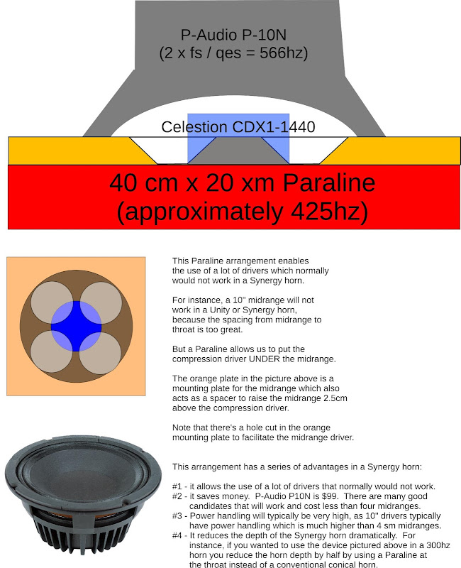
Basically, this is a coaxial arrangement with the compression driver UNDER the cone of the midrange driver.
This allows us to use a TON of additional midranges, potentiall raises power handling, etc.
It just occurred to me, you could go REALLY nuts and nest a compression driver in a midrange in a woofer :O
In your pictorial, what does the second layer look like?
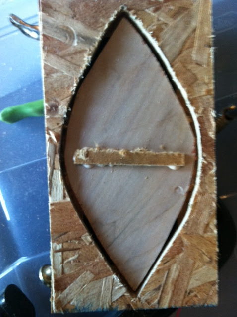
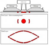
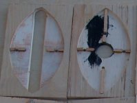
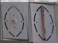
Pretty much like this. Eye-shaped. Directions on how to draw this are in this thread and in the patent. The second and the fourth layers in an eye-shaped Paraline look virtually the same. (This is the fourth layer not the second.)
The pictures below might help you see how the parts work.In your pictorial, what does the second layer look like?
They are the "guts" to Paralines using a 1.4" exit EV DH1AMT.
The 3" diaphragm allows for a crossover low enough to make 8" or 10" cones viable for PA use. That said, at typical home levels, most 1" exit drivers are perfectly capable on a large Paraline horn of response down to the 600 Hz range at "ear bleed" levels.
It should be noted that this equal path length Paraline has a vertical HF dispersion of only a few degrees, great for a line array, but for those thinking of using a just one or two drivers the "eye" needs to be thinner to provide a more diverging wavefront appropriate for home use.
Art Welter
Attachments
Art - Apologies, but could you explain which bit of the eye needs to be thinner? I assume the exit slot? And there's presumably a formula? I'd like to keep the vertical dispersion very narrow and then figure out what horizontal angle works best in my sitting room.
NB: and again I assume you can't reduce the exit slot below the size of the wavefront at that point without causing problems?
Thank you
NB: and again I assume you can't reduce the exit slot below the size of the wavefront at that point without causing problems?
Thank you
I'm not Art, but I'll take a stab at this ")
If you want narrow vertical dispersion, set the height to equal the width multiplied by two. That will give you a flat wavefront (zero degrees of vertical coverage)
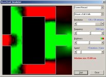
Play with the wave simulator in Hornresp, and you'll notice that there's no directivity control when the wavelength is larger than the dimensions of the slot. For instance, with a slot that's 20cm tall by 4cm tall you'll lose directivity at approximately 1700hz and 8500hz, respectively. The formula is speed of sound divided by the dimensions of the radiator.
If you want narrow vertical dispersion, set the height to equal the width multiplied by two. That will give you a flat wavefront (zero degrees of vertical coverage)
Play with the wave simulator in Hornresp, and you'll notice that there's no directivity control when the wavelength is larger than the dimensions of the slot. For instance, with a slot that's 20cm tall by 4cm tall you'll lose directivity at approximately 1700hz and 8500hz, respectively. The formula is speed of sound divided by the dimensions of the radiator.
As far as horizontal angle goes, it will largely be dictated by the horn that you mount to the Paraline. Most eye shaped paralines will have virtually no pattern control in the horizontal axis due to their narrow width.
Note that these rules apply to ALL radiators. A Paraline's mouth behaves like a ribbon, a ribbon with a delay.
Area of the mouth is simple. It's (Paraline height * pi * internal height of Paraline)
For instance, if the inner duct in your Paraline is 0.635cm and the height is 20cm, the area of the mouth is (20 * 3.14159 * 0.635) or 39.9. Since we know the height of our Paraline is 20cm, our width is a hair under 2cm. You may notice that the Danley Paralines are wider than mine. That's bcuz there's a phase plug in the center, which necessitates a wider mouth than mine.
Art - Apologies, but could you explain which bit of the eye needs to be thinner? I assume the exit slot? And there's presumably a formula? I'd like to keep the vertical dispersion very narrow and then figure out what horizontal angle works best in my sitting room. ...
Not the exit slot, the eye shaped slot. It's simple geometry.
The vertical dispersion is determined by the path lengths within the line.
The "standard" Paraline emits a "plane" wavefront, in theory zero vertical dispersion. If you measure from the driver to the nearest part of the mouth, the path length is the same all around the line - all parts of the wavefront from the driver arrive at the mouth at the same time. If you want to make a diverging wavefront with some vertical dispersion, you make the eye shape "slimmer" so that the wavefront arriving at the middle of the exit slot arrives earlier than that at the ends. Making the eye "rounder" will tend to focus the wavefront to a point in front of the line, though I don't see what application this would have for home audio.
Patrick - thanks. That's all I needed. I'd read Art as talking about a diverging horizontal wavefront being caused by a thinner eye, thinking he meant the exit slot. But of course he meant the overall eye shape, which impacts vertical directivity too - as I'd realised from the patent and Don kindly pointed out.
This just might be my ticket for actually building a synergy horn... Everything is just so convenient.
And furthermore, if the "no waves form inside" theory actually works this should also be a HOM / diffraction free horn. With some round-overs at the exit hole and some optimized deflectors/phaseplugs this should actually be a rather hi-fi device.
Coolest thing I've seen in a while.. Thanks, again, Tom Danley and Patrick Bateman!
In Patrick Bateman's pic of the coaxial Paraline he mentions using this in a Synergy horn to reduce the depth of the horn. I've seen this mentioned elsewhere, and I'd like to know if my thinking makes any sense.
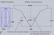
Since the Paraline is a horn itself do we use the internal path-length of the Paraline to determine the length of the horn that it attaches too? In my drawing I have a paraline tuned to about 620hz with a 5.4" path-length (I used Bateman's spreadsheet to get 40 deg vertical coverage). The drawing of the horn is a top view and it's dimensions were determined with bwaslo's spreadsheet here: http://www.diyaudio.com/forums/mult...ur-own-synergy-more-simple-conical-horns.html
As you can see it's a 60 deg conical in the horizontal plane and its' 20" width is about 670hz. With a comp driver at the throat the horn would be about 11" long. Is it as simple as putting the Synergy paraline 5.4" from where the CD throat would be, keeping the width of the horn the same as it would be on a regular Synergy to keep the coverage angle and mouth width the same?
I can't help but think that it isn't this simple. I understand that a paraline has no real directivity control in the horizontal plane due to the small width of the exit slot. That being the case, wouldn't we want the throat of the horn the paraline couples to to be the same width as the paraline exit slot? To keep the same coverage angle and mouth width the horn would be back to 11"..............I'm confused, and obviously don't know a whole lot about horns. Thanks
Since the Paraline is a horn itself do we use the internal path-length of the Paraline to determine the length of the horn that it attaches too? In my drawing I have a paraline tuned to about 620hz with a 5.4" path-length (I used Bateman's spreadsheet to get 40 deg vertical coverage). The drawing of the horn is a top view and it's dimensions were determined with bwaslo's spreadsheet here: http://www.diyaudio.com/forums/mult...ur-own-synergy-more-simple-conical-horns.html
As you can see it's a 60 deg conical in the horizontal plane and its' 20" width is about 670hz. With a comp driver at the throat the horn would be about 11" long. Is it as simple as putting the Synergy paraline 5.4" from where the CD throat would be, keeping the width of the horn the same as it would be on a regular Synergy to keep the coverage angle and mouth width the same?
I can't help but think that it isn't this simple. I understand that a paraline has no real directivity control in the horizontal plane due to the small width of the exit slot. That being the case, wouldn't we want the throat of the horn the paraline couples to to be the same width as the paraline exit slot? To keep the same coverage angle and mouth width the horn would be back to 11"..............I'm confused, and obviously don't know a whole lot about horns.
ThanksAttachments
- Home
- Loudspeakers
- Multi-Way
- Square Pegs