A little closer to the clear drawing I was shooting for.
Room under those sonotubes to hide midbass drivers
if you get to thinking unity...
The subtle thing here thats cool: Is the expansion from
roughly 45 degrees to 90 degrees is matched to fully
fill the horn without the high frequencies that usually
couldn't follow that change beaming down the center...
Lookie them curves! Bent the opposite way you have
become used to seeing of late. Not the usual paraline.
Remember, this is a Smith horn: The panel, slot, and
constant directivity are all horizontally oriented in this.
Attachments
Last edited:
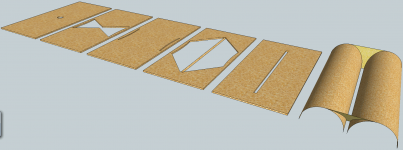
A little closer to the clear drawing I was shooting for.
Room under those sonotubes to hide midbass drivers
if you get to thinking unity...
The subtle thing here thats cool: Is the expansion from
roughly 45 degrees to 90 degrees is matched to fully
fill the horn without the high frequencies that usually
couldn't follow that change beaming down the center...
Lookie them curves! Bent the opposite way you have
become used to seeing of late. Not the usual paraline.
Remember, this is a Smith horn: The panel, slot, and
constant directivity are all horizontally oriented in this.
Now that's an interesting concept.....are you going to build it?
A little closer to the clear drawing I was shooting for.
Room under those sonotubes to hide midbass drivers
if you get to thinking unity...
The subtle thing here thats cool: Is the expansion from
roughly 45 degrees to 90 degrees is matched to fully
fill the horn without the high frequencies that usually
couldn't follow that change beaming down the center...
Lookie them curves! Bent the opposite way you have
become used to seeing of late. Not the usual paraline.
Remember, this is a Smith horn: The panel, slot, and
constant directivity are all horizontally oriented in this.
Looks good, but keep in mind that the expansion rate is going to be realllly slow. That's good for low frequencies, not so good for tweeters.
Why (specific to this unique case) not good for tweeters?
more HOMs perhaps ?
Sorry for the delay... have built and measured many an antenna. Yes, coaxial coplanar. Like the one described, what velocity factor did you use to correct stub length? Have a GH4N3 with narrods and top hats. Works a peach.
/ot
Interesting design and actually have all the materials on hand, including the sonotubes (Sakrete). Actually there is enough room in the tubes for a 6.5" mltl sub that'll hit 26 quite well I've designed. Woofer on top, port out the lower back. The width would aid BS to ~240Hz(ottomh) along the line.
I'm not saying I'm on board to try due to another design thats been put on hold... car accident, totalled, at fault driver never had a license and their insurance was recended for breach of contract kinda crap
It's similar in size and uses 12"tubes for roundovers. Big on stature yet rather thin profile (9-10" deep) active 3way. Am so close to making this a wrap can taste it. Uggg, life
I'm not claiming anything I've drawn will work. And not building anything
this weekend, nor till I get a couple of days off work, like probably never.
Was supposed to replace disintegrating tires on my truck and didn't even
do that today. I'm so fatigued, I can't even imagine starting.
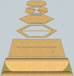
But I can imagine this:::
Since Patrick thinks the expansion is too slow, lets go crazy with that idea.
Manifold up to 4 compression drivers, here shown with only 2. So much
versatile room under those roundovers to hide all kinds of stuff, why have
anything on the back to interfere with hanging flat against the wall?
this weekend, nor till I get a couple of days off work, like probably never.
Was supposed to replace disintegrating tires on my truck and didn't even
do that today. I'm so fatigued, I can't even imagine starting.
But I can imagine this:::
Since Patrick thinks the expansion is too slow, lets go crazy with that idea.
Manifold up to 4 compression drivers, here shown with only 2. So much
versatile room under those roundovers to hide all kinds of stuff, why have
anything on the back to interfere with hanging flat against the wall?
Attachments
Last edited:
more HOMs perhaps ?
No HOM across a sandwich gap shorter than 1/4 wave of treble.
If you want to attenuate side to side longways modes, open cell
foam is easily obtained in sheet form.
That ginormous paraline we built didn't sound like no homster,
even without any foam in it...
Last edited:
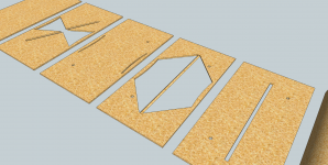
No functional difference, just cutting corners for weight.
Still lots more do-nothing material here could be pruned.
I'd probably just go with simple and heavy drawing 701...
better get cracking then. I've rebuilt my table saw power switch so that's available in addition to the rest of our tools..
better get cracking then. I've rebuilt my table saw power switch so that's available in addition to the rest of our tools..
I can't wait to see the results!
Cookiemonster77, in post #600, you show a design similar to what I've had in my head for a while.
Did you make any progress with that approach?
Not yet, mostly because I didn't have time try it out. What is the main differences between your idea and what I posted?
So the reason my Paraline has a square mouth instead of a long skinny one is that I was stacking a Paraline on a Paraline. By doing that, you cut the footprint in half.
Sorry for looking like I'm bumping this thread! I just keep getting ideas, and return to it!
This paragraph has me thinking... how low would it be feasible to go? I was thinking along the lines of Nate Hansen's design, but maybe to allow a crossover of 150Hz (not pattern controlled, necessarily), with a horn flare as the final stage?
1) Think in terms of compression ratios that work with high excursion horn loaded drivers and you can see the Paraline is not particularly suited for VLF potential, and is unwarranted for that application, though it is is not detrimental to applications going as low as 150 Hz.1)This paragraph has me thinking... how low would it be feasible to go?
2)I was thinking along the lines of Nate Hansen's design, but maybe to allow a crossover of 150Hz (not pattern controlled, necessarily), with a horn flare as the final stage?
2) Not familiar with the design you are referring too, but Tom Danley designed the Paraline specifically to provide a tightly prescribed vertical HF pattern control with a horizontal diffraction pattern determined by the conical waveguide wall angles.
What are you looking for specifically in terms of frequency response, sensitivity, and pattern control?
Art
1) Think in terms of compression ratios that work with high excursion horn loaded drivers and you can see the Paraline is not particularly suited for VLF potential, and is unwarranted for that application, though it is is not detrimental to applications going as low as 150 Hz.
2) Not familiar with the design you are referring too, but Tom Danley designed the Paraline specifically to provide a tightly prescribed vertical HF pattern control with a horizontal diffraction pattern determined by the conical waveguide wall angles.
What are you looking for specifically in terms of frequency response, sensitivity, and pattern control?
Art
Art, as always, thanks for your informed reponse!
I'll dig up some links of Nate Hansen's paraline Synergy. It was mentioned quite a while back in this thread, briefly:
http://www.diyaudio.com/forums/multi-way/217298-square-pegs-43.html#post3458538
DIY Synergy/Unity spreadsheet
That's all I could find for now.
I did wonder about the compression ratio side of things - it seems like strong motors would be a necessity. Taking the Synergy approach however, would it be possible to mount a number of weaker drivers to the same paraline to compensate?
Frequency response: something that's feasible (150Hz was an ideal
), so 200 or 300HzSensitivity: nothing essentially extreme. "In the 90s"?
Pattern control: Something like Bill Waslo's Synergy, which I think goes down to 320Hz (from memory)
Edit: Patrick, did you ever post the plans of the Paraline you'd built in post #1? Also, would adding a horn flare to that allow a lower frequency response (i.e. lower than the 500Hz stated in the video)?
Last edited:
Exactly why I bought a pair of 4ohm 3fe22, to find out...Could a small 3in full range driver be used at the center rather than a CD? It seems that cone drivers can be used at the periphery to supplement the HF from a CD. What about having no CD and only cone driver? Is there any benefit to this?
This tiny magnet 3" thing doesn't impress to look at.
I hope they can live up to spec and blow me away.
- Home
- Loudspeakers
- Multi-Way
- Square Pegs