Maybe its optical illusion, but paraline slots in middle look shorter
than those near the ends. Play with the contrast you can see it...
If the vertical pattern is tight as demonstrated in the video, why
this apparent taper?
Yay people are starting to realize some of the neat things you can do with these
")
I seriously think this device is more clever and elegant than even the layered combiner.
Here's what's going on IMHO:
Let's say you have a conventional line array.
Each box is 40cm tall, with a center to center spacing of 40cm.
At 213hz (one quarter wavelength), the elements of the array combine constructively. This is due to the tight spacing.
But as we go higher in frequency, we get a complex interference pattern.
By 1.6khz it's a complete mess.
Now most arrays put the compression drivers into a waveguide, to narrow the vertical pattern.
Let's say we opt for ten degrees of vertical coverage. Unfortunately, that requires a waveguide that's 228.6cm deep! So now you have a box that's 40cm tall by 228.6cm deep. Not too practical.
So they cheat. They use a vertical coverage angle that's too wide, and now the high frequencies in the array overlap.

You can see the overlap in this B&C
The Paraline solves all of that. You get a wavefront that's the shape of a ribbon. So now you can pack lots of drivers vertically.
The last piece of the puzzle is the curvature.
All of the Synergy horns produce a wavefront that's basically like a cone shaped piece of a sphere.
Since this FR Paraline is a Synergy Horn, it needs to produce a curved wavefront.
To do that, the Paralines in the center of the FR Paraline need to 'lead' the Paralines on the edge of the FR Paraline. Not a lot; about four centimeters. So gradually scaling each Paraline in the line curves the wavefront.
If you *really* wanted to go nuts you could make the Paralines asymmetrical. That would seriously be splitting hairs, but high frequencies *are* very short, so an asymmetrical Paraline might not be completely crazy.
Here's how I'd make the line if it were me, from top to bottom:
1) 21.5 cm tall
2) 20 cm tall
3) 18.5 cm tall
4) 17 cm tall
5) 17 cm tall
6) 18.5 cm tall
7) 20 cm tall
8) 21.5 cm tall
A difference of 4.5cm might not seem like much, but 10khz is 3.4cm long. So even a difference of one centimeter counts.
Hi guys
Patrick, you Art and a couple others here are often right or are partly right in your guesses.
Now it wouldn’t be fun for the companies we compete against if I didn’t make new stuff or if everything was obvious haha. On the other hand, one must be consistent with how sound works or it’s just marketing so how it works can be figured out..
I can add a few clues though. If you keep all of these in mind, you will see the framework the answer must fit within.
Consider fig #7 I think it is in the synergy horn patent.
What conditions / rules must one live within to avoid horn pattern flip down to / below pattern loss frequency?
What happens if one were to move the source of an “eye” paraline up or down slightly?
What happens to time of propagation through one if one used different size paralines as Ken keenly observed?.
Consider the actual horn path length is not the easy to calculate cross section but that of a pressure radiated at the throat and bounded by solid walls confining the pressure to a fractional space and so has a protruding mouth bubble effect which can be significant.
Art, your right, I don’t imagine we will ever make a line array. A true line array has so many problems related to it’s geometry (unless one made one floor to ceiling) that the need to be shaped, curved or tapered in amplitude to make them behave more like a point source. With the exception of the Yorkville units with the paraline and synergy horn arrangement, most are made with acoustic sources much too far apart to combine into one and so radiate as individual sources.
It is possible to radiate much less to vastly energy outside the desired pattern with a large horn and have some other advantages. Where line arrays deliver a spectrum dictated by the vector sum of all the arriving sources, a single impulsive event is also spread out in time because of the different time of arrival from each source.
In other words, by having an interference pattern created by many individual sources one can use self cancellation and make the rate the spl falls off less than being on axis of a simple point source. This self cancellation is great for companies wanting to sell lots of cabinets, amplifiers and dsp and not so great if one wants intelligibility, economy or musical reproduction.
A wide band point source like Synergy horns only delivers one impulsive arrival, the large ones radiate much less energy out side of the desired pattern than big name line arrays and with the exception of hf air absorption also has the same spectral balance at any working distance, by using the directional lobe, one can in some cases produce only a 2 or 3 dB variation in spl over a vast area, even a stadium.
Best,
Tom
Hey if you have facebook and headphones, at the company FB page, below that paraline video is one for the Caleb which might be humorous. It’s a new stadium loudspeaker, a 10 foot tall constant directivity Synergy horn with over 100 drivers.
I should really get some work done, but I had to take a stab at this
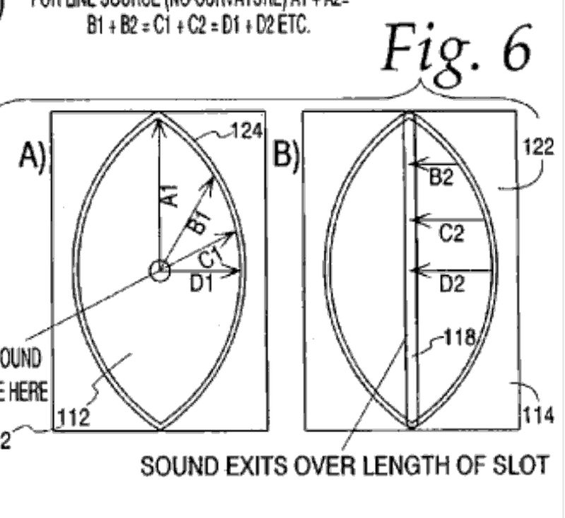
Here's a Paraline, from the patent
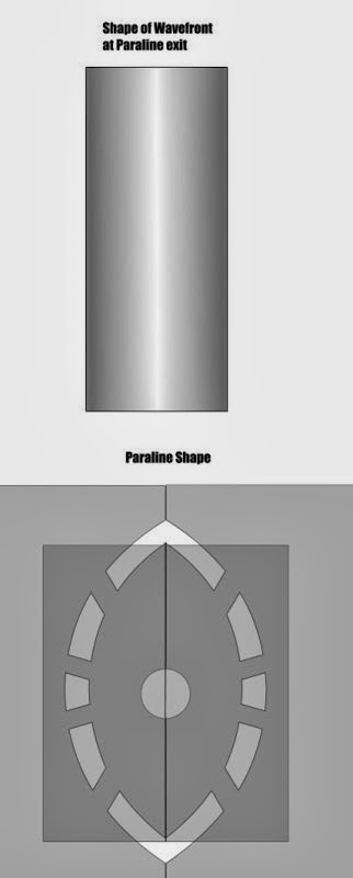
If the height is twice the width, you get a flat wavefront. That's because the distance A1 is the same as the distance D1 plus D2. Therefore, sound exits the two points at the same time.
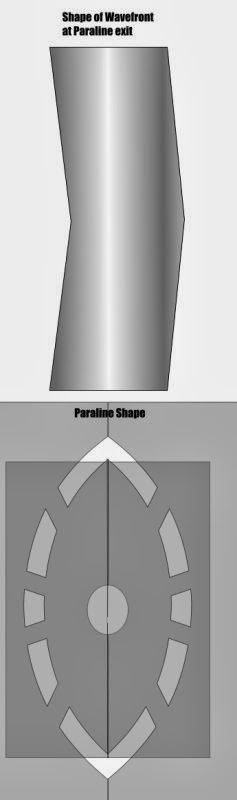
Stretch it out in the vertical axis, and now sound exits the center before it exits the edge. Now you have a wavefront that's diverging. If you keep the width of the Paraline constant and you add an inch to the height, then the sound that exits at the edge of the Paraline will be delayed by one half inch or 0.037ms. (Because the sound is travelling radially, that's why it's half.)

Take that Paraline from the first case and move the throat up, and now the wavefront is pointed *down*.
You can also combine this in some rather odd ways. It's possible to have a wavefront that's J shaped, or a converging wavefront. You can use the Paraline to delay sound. You can even delay it based on angle. For instance, if you want the speakers to face one way but you want the wavefront to curve another, you can do that.
As you can imagine, there's limits to all of this. Not sure how much curvature you could get away with, but there's one way to find out...
Here's a Paraline, from the patent
If the height is twice the width, you get a flat wavefront. That's because the distance A1 is the same as the distance D1 plus D2. Therefore, sound exits the two points at the same time.
Stretch it out in the vertical axis, and now sound exits the center before it exits the edge. Now you have a wavefront that's diverging. If you keep the width of the Paraline constant and you add an inch to the height, then the sound that exits at the edge of the Paraline will be delayed by one half inch or 0.037ms. (Because the sound is travelling radially, that's why it's half.)
Take that Paraline from the first case and move the throat up, and now the wavefront is pointed *down*.
You can also combine this in some rather odd ways. It's possible to have a wavefront that's J shaped, or a converging wavefront. You can use the Paraline to delay sound. You can even delay it based on angle. For instance, if you want the speakers to face one way but you want the wavefront to curve another, you can do that.
As you can imagine, there's limits to all of this. Not sure how much curvature you could get away with, but there's one way to find out...
Last edited:
Patrick,Let's say we opt for ten degrees of vertical coverage. Unfortunately, that requires a waveguide that's 228.6cm deep! So now you have a box that's 40cm tall by 228.6cm deep. Not too practical.
So they cheat. They use a vertical coverage angle that's too wide, and now the high frequencies in the array overlap.
The Paraline solves all of that. You get a wavefront that's the shape of a ribbon. So now you can pack lots of drivers vertically.
10 degree HF angle would only work for a "line array" of four or five units, which would technically be a vertical array, not a line array.
Most industry accepted line arrays use HF throat guides that use equal path length slots to achieve similar results to the Paraline, a HF wavefront that diverges only slightly.
The Paraline happens to be the thinnest, but there are many examples under 14 centimeters that have vertical HF patterns of only a few degrees.
Art
The specs are up on Danley's website. Says it uses eight 5" co-ax drivers. Guessing the same BMS 5" used in SM-60 Synergy horn.
http://www.danleysoundlabs.com/danl...13/10/Paraline-FR-Preliminary-Spec-sheet1.pdf
http://www.danleysoundlabs.com/danl...13/10/Paraline-FR-Preliminary-Spec-sheet1.pdf
The specs are up on Danley's website. Says it uses eight 5" co-ax drivers. Guessing the same BMS 5" used in SM-60 Synergy horn.
http://www.danleysoundlabs.com/danl...13/10/Paraline-FR-Preliminary-Spec-sheet1.pdf
An interesting 'vindication' of the Synergy horn is that the full range Paraline has eight tweeters and can hit 130dB. But there are half a dozen Synergy horns that can hit the same SPL with just one tweeter!
But none of them are as small as the 'skinny big horn'.
Hoffman's Iron Law rears it's ugly head again.
It's an expensive solution too. Eight of those coax drivers are about $3200. But the driver complement in an SH-50 is about $870. ($150 for a compression driver, about $120 for the midranges, and another $600 for the midbasses.)
If you have the space, I can see how the 'normal' synergy horns are a no-brainer.
Then again, if cost is no object, the SBH is smaller, has a narrower beamwidth, and it's output level is comparable.
For home theater, that's pretty compelling. My tiny little apartment in San Diego doesn't have room for big speakers.
Last edited:
Even if phase terminates properly for line array or curved for synergy:
Are there any consequences that amplitude is greater at the center than
the ends? More degrees of the driver pie per linear unit of the exit slot...
That's not a defect, that's a feature!
The fact that the output level is higher at the middle makes the Paraline easier to array.
I think I remember Mike Hedden saying they are using ferrite drivers instead of neodymium due to cost. That would point to this one unless BMS is making a custom driver for them, which isn't out of the question.
BMS Pro 5C150
BMS Pro 5C150
An interesting 'vindication' of the Synergy horn is that the full range Paraline has eight tweeters and can hit 130dB. But there are half a dozen Synergy horns that can hit the same SPL with just one tweeter!
I think the SPL limit might be imposed by the cones and not the compression drivers on the coaxials. Actually, i'm pretty sure. Each cone is limited to 130W and if you add 10dB for horn loading and another 9dB for multiple drivers you end up at 130.14dB.
Hi Guys,
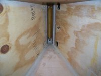
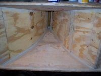
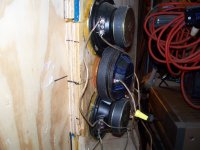
A interesting thread for sure,I have built 2 speakers of this design Thanks for all your posts,I couldn't do this without you guys! They work very well,most people remark at how clear they are,I am using a Deq and a dcx 2496 so I can tune electrically almost anywhere,but I was wondering if I can improve this setup by designing the correct size cutouts inside to work as a passband ,maybe work with minimum E correction,so is there a size paraline cutout I can make for this ,or a way to figure the upper and lower cutoffs,any suggestion are welcomed!
Thanks alot,
NS
Attachments
Hi Guys,
A interesting thread for sure,I have built 2 speakers of this design Thanks for all your posts,I couldn't do this without you guys! They work very well,most people remark at how clear they are,I am using a Deq and a dcx 2496 so I can tune electrically almost anywhere,but I was wondering if I can improve this setup by designing the correct size cutouts inside to work as a passband ,maybe work with minimum E correction,so is there a size paraline cutout I can make for this ,or a way to figure the upper and lower cutoffs,any suggestion are welcomed!
Thanks alot,
NS
First off, great job! I'm not sure what you mean by the "cut outs". Can you go into more detail on your question?
Hi JLH,
You got some nice toys also and I have read alot of your posts ,especially on compression driver comparisions,very informative!
I ment by cutouts the actual size you make the width and lenght of the eye ,I have understood that the .25 " slot is used to pass freq. around 20 k and under so that is a constant.NOW the size you make the actual perimeter can change ie bigger or smaller,correct?So I'm thinking,(look out),lol.........
If you make the size of the eye 4" wide and the hieght acording to the string method will that the pass freq in the range of say mid range like (guessing) 8khz to 18khz or by the same token make it 12" long and would that give the lower freq with a upper say 3khz rolloff,I'm looking to design the lenth to fit the passing of signal like a cross over would normally do,but do it at the speaker/size of the paraline,OR door #3 Is this not going to work at all,lol.
What happens when you stack these like make 2 or 3 of them together?I know it increases path length,so timing changes ,correct?
I hope that's a little clearer ,lol. Thanks for some help!
NS
Last edited:
Question for Patrick Bateman and JHL
Hi Patrick, JHL,
you have several times discussed the fact that the flare rate varies for conical horn as a function of a distance. Patrick also posted several times a chart purporting to depict an "expansion" in [Hz] as a function of distance in [cm], cf. at least post 540 in this thread.
I seem to have difficulties in understanding how you use the terms flare rate and expansion. in my understanding, a flare rate is defined as a (rate of change of wave-front area with distance)/(wave-front area), which I approximate as (rate of change of area with distance)/(area). Clearly this does not have units of [Hz].
Consequently, could you provide your definition of the terms as you use them?
Kindest regards,
M
If in doubt, read the patent
Tom's detailed very thoroughly how to build these.
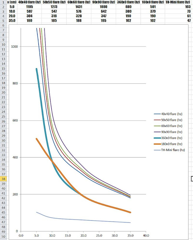
This illustration shows the 'local flare rate' versus distance for various horn types, including four different sizes of conical horn and two different Paraline configurations.
One of the fundamental aspects of a Unity or Synergy horn is that the flare rate is changing very very quickly at the throat. See how the curve looks like a hockey stick for the first ten centimeters? This is also the reason that a lot of people have had good results by 'eyeballing' the midrange taps. As long as it's somewhere around 5-10cm down the throat you're in the 'zone' where the flare rate is expanding very very quickly.
If you look at an exponential horn, the rate of change is much slower. See how the area doesn't expand as quickly?
The reason you can calculate the flare rate at any point along the throat is that a Unity or Synergy horn is basically a horn feeding a horn feeding a horn. Picture each segment as an independent horn that's stacked together.
So that's how you calculate the local flare rate. (Hornresp helps a lot - and JLH has documented how to do that in this thread.)
Note that if it wasn't for the rapid expansion of the flare rate, the Unity / Synergy horn concept wouldn't work. For instance, if you used an exponential flare you'd run into a catch 22. Basically if you tried to tap your midranges into the horn they'd be too far from the throat. The only way to get around this is to tap it into the wrong location (which will screw up the midrange response), use a compression ratio that's too high for the midranges (which will sound terrible), or use very very small midranges.
Last edited:
The sensitivity of the SBH-10 is only 100 dB, only +10 dB over the 90 dB cone drivers (assuming the BMS 5C150 is used), no horn addition is needed to achieve 130 dB with 1000 watts.I think the SPL limit might be imposed by the cones and not the compression drivers on the coaxials. Actually, i'm pretty sure. Each cone is limited to 130W and if you add 10dB for horn loading and another 9dB for multiple drivers you end up at 130.14dB.
100 dB 1w
110 dB 10w
120 dB 100w
130 dB 1000w
Factoring in a couple dB of power compression, makes sense to reccommend an amplifier capable of 2400 watt peaks to achieve the 134 dB maximum program out.
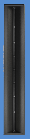
The "large horn with an effective path length of 25 feet" is a marketing device, it appears that the approximately 5 feet of Paraline path has been added to the 15 feet of path length from the center of the horn to the center of the back of the cabinet x 8, plus another 5 feet from the center of the front of the cabinet over the top and to the center of the back
. The outer Paralines are about 8.3 inches in height, next pair 6.7", next pair 6", center pair about 5.3", effectively "bowing" the line by 3", eliminating the need for "power shading" the outer tweeters as is done in other small line arrays to reduce HF loss due to destructive interference.
Attachments

Last edited:
The vertical height of the Paraline does not affect the frequencies that can be passed, the frequency response is determined by how low the driver can go.I ment by cutouts the actual size you make the width and lenght of the eye ,I have understood that the .25 " slot is used to pass freq. around 20 k and under so that is a constant.NOW the size you make the actual perimeter can change ie bigger or smaller,correct?So I'm thinking,(look out),lol.........
If you make the size of the eye 4" wide and the hieght acording to the string method will that the pass freq in the range of say mid range like (guessing) 8khz to 18khz or by the same token make it 12" long and would that give the lower freq with a upper say 3khz rolloff,I'm looking to design the lenth to fit the passing of signal like a cross over would normally do,but do it at the speaker/size of the paraline,OR door #3 Is this not going to work at all,lol.
What happens when you stack these like make 2 or 3 of them together?I know it increases path length,so timing changes ,correct?
I hope that's a little clearer ,lol. Thanks for some help!
NS
Varying the height and path length of the Paralines can be used to create a cabinet that has a flat front, yet behaves like it is arced.
The net effect is similar to the "beam steering" used in some line arrays, but does not require multiple delays and amplifiers.
Going back to this diagram, I think the problem you run into when you try to make a Paraline fairly large is that the compression ratio gets too high.
If you look at that diagram, you'll notice that the flare rate of the conical horns and the radial horns are similar for about the first ten centimeters or so.
After that first ten centimeters or so, the area of all the conical horns exceeds the area of the radial horns by a lot.
The reason for this is simple: the radial horns are expanding in one dimension, the conical horns are expanding in two. (width *and* height.)
That leaves you three option:
Option One:
The first option is to limit the size of the Paraline to about 20cm in height. The reason that 20cm is the 'magic number' is that the wave is expanding radially. So a 20cm Paraline has a pathlength of 10cm. Any longer than that, and the compression ratio starts to get too high.
Option Two:
The second option is to add a vertical expansion. This is tricky for a couple reasons. First, it will be *really* hard to manufacture. Good luck building that with a table saw. Second problem is that the reflection at the correction slot will get worse as the size of the correction slot gets larger.
Option Three:
The third option is to use really tiny drivers. Compression ratio is dictated by the size of the speaker and the area in front of it. So if you can't make the area larger, you can make the driver smaller. Obviously, the law of diminishing returns will play a factor here. I think it would be hard to make a Paraline much bigger than 20-40cm.
Now, obviously you can make an array of Paralines, which is exactly what the SBH-10 is.
- Home
- Loudspeakers
- Multi-Way
- Square Pegs