Hi. I'm completely new to this. Can someone explain what order I need to use these different tools in?
I have Hornresp, I've entered all the Thiele-Small Parameters etc. I hit calculate but not sure what values I should be exporting into the Boxplan spreadsheets.
I really need to put together a list of instructions on how to use the spreadsheets, along with a few worked examples
") .
.Here's a simple outline:
1. Use HornResp to come up with a suitable TH design for your driver (BTW, the driver you chose may not be the best driver for this type of alignment unless you want to go really low, and the folds that are covered in my spreadsheets are more for pro audio builds).
2. Take a note of the net volume of the simmed TH, then add about 10~15%. Let's call this V
3. Choose starting box dimensions to achieve volume V and enter these into the spreadsheet.
4. Enter the dimensions of the driver into the spreadsheet.
5. If the spreadsheet indicates that S1 or S4 (or S4), needs to be entered, do so, using the values from your HornResp sim.
6. Adjust panel sizes in the spreadsheet until the horn expansion (lower graph is a smooth as possible).
7. If the other calculated HornResp parameters in the spreadsheet are not a close match for those in your sim, try adjusting the box dimensions a bit, then repeat from step 6.
8. Once you're close enough, replace the HornResp parameters in your sim with the ones from the spreadsheet. If you don't like the results, repeat from step 6
.Thanks for the reply!
I've been reading around this subject for a couple of weeks now, and the material available is too informative if anything! It feels like I have to study for a Ph.D. in speaker design to get anywhere.
Even one worked example from start to finish would be INCREDIBLE!
It would really help make sense of all the terminology and interrelation of variables in all these calculations.
Redoing the "Keystone"....
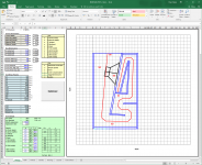
Well, it's been a while since I've posted an update here, so here's one. I'm working on a design spreadsheet that "improves" (sacrilege, I know) on the Keystone-type build by converting the fold to a dual-expansion TH (that narrows the passband, by increases efficiency), moving the driver to the bottom of the enclosure (to increase stability) and finally lengthening L12 as the longer L12 is, the easier it is to damp out of band peaks by stuffing this section.
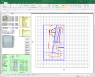
The spreadsheet is still a work-in-progress as I've got some unused space (highlighted in the image) in the horn and I'm thinking of including in cone compensation (to address the usual upper dip in the passband that can happen when doing a TH without cone compensation), but this spreadsheet features something my previous spreadsheets didn't feature - Optimization macros! Just put in the desired external measurements and the expansion angle, then hit the "[Optimize!]" button a few times until all the error values in the table reach zero, and you're done. It usually takes about 7 or 8 hits of the button, but the process is quick, and it's certainly faster than trying to optimize the layout by hand. Just don't make any huge changes to the measurements, as the optimization routine has no limiting built in and you could end up with unusual results.
Note that the spreadsheet is unfinished (some of the functions are not working) and of course it contains macros, so you'll have to enable macro execution when you open it, but I've already used it to come up with a 100dB 40 Hz~300 Hz TH based on the Kappalite 3012LF-4 driver that will fit perfectly in my car's trunk for transport.
Well, it's been a while since I've posted an update here, so here's one
. I'm working on a design spreadsheet that "improves" (sacrilege, I know) on the Keystone-type build by converting the fold to a dual-expansion TH (that narrows the passband, by increases efficiency), moving the driver to the bottom of the enclosure (to increase stability) and finally lengthening L12 as the longer L12 is, the easier it is to damp out of band peaks by stuffing this section. The spreadsheet is still a work-in-progress as I've got some unused space (highlighted in the image) in the horn and I'm thinking of including in cone compensation (to address the usual upper dip in the passband that can happen when doing a TH without cone compensation), but this spreadsheet features something my previous spreadsheets didn't feature - Optimization macros! Just put in the desired external measurements and the expansion angle, then hit the "[Optimize!]" button a few times until all the error values in the table reach zero, and you're done. It usually takes about 7 or 8 hits of the button, but the process is quick, and it's certainly faster than trying to optimize the layout by hand. Just don't make any huge changes to the measurements, as the optimization routine has no limiting built in and you could end up with unusual results.
Note that the spreadsheet is unfinished (some of the functions are not working) and of course it contains macros, so you'll have to enable macro execution when you open it, but I've already used it to come up with a 100dB 40 Hz~300 Hz TH based on the Kappalite 3012LF-4 driver that will fit perfectly in my car's trunk for transport
.Attachments
Brian,I'm working on a design spreadsheet that "improves" (sacrilege, I know) on the Keystone-type build by converting the fold to a dual-expansion TH (that narrows the passband, by increases efficiency), moving the driver to the bottom of the enclosure (to increase stability) and finally lengthening L12 as the longer L12 is, the easier it is to damp out of band peaks by stuffing this section.
..I've already used it to come up with a 100dB 40 Hz~300 Hz TH based on the Kappalite 3012LF-4 driver that will fit perfectly in my car's trunk for transport
Your design sims well, but bears little resemblance to the Keystone, named after the exit shape, not the horn path, which is quite different from yours.
Don't understand "moving the driver to the bottom of the enclosure", your layout shows the driver at the top of the cabinet with the exit to the sky. If you lay it down, the design is quite deep, taking up a lot of real estate.
Stuffing reduces out of band peaks as well as in band sensitivity.
Based on my experience with using the Eminence 4015LF in the Keystone, the extra sensitivity from the light mms is negated by the gnarly distortion as the cone "doth protest too much" when pushed anywhere near Xmax ;^).
Cheers,
Art
Your design sims well, but bears little resemblance to the Keystone, named after the exit shape, not the horn path, which is quite different from yours.
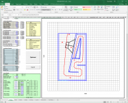
Yup, I had to redo part of the fold, to incorporate the dual expansion. It's a still a W.i.P. as I don't like having unused space in a fold. And there will be more unused space when I incorporate the cone compensation.
Don't understand "moving the driver to the bottom of the enclosure", your layout shows the driver at the top of the cabinet with the exit to the sky. If you lay it down, the design is quite deep, taking up a lot of real estate.
Rotate the image 180 degrees
. The mouth is pictured as firing out the top (bottom!) because it's just easier to sim that way. The mouth can be moved to facing the driver in the actual build, and any response changes should be minor. The builder can fiddle around with the shape of the mouth in the actual build as per the "Keystone" build. Stuffing reduces out of band peaks as well as in band sensitivity.
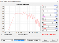
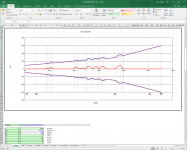
If L12 is long, the impact of any stuffing in that section is limited primarily to frequencies above 120 Hz or so and does not significantly affect passband sensitivity. Well, at least HornResp says so
. Stuffing anywhere else in the TH does impact passband sensitivity though. Based on my experience with using the Eminence 4015LF in the Keystone, the extra sensitivity from the light mms is negated by the gnarly distortion as the cone "doth protest too much" when pushed anywhere near Xmax ;^).
The 4015LF is quite different to the 3012LF, so hopefully my experience is different. In any case, I'm keeping the CR pretty low for this particular design, in the hope I don't run into that problem. Also, by using a spreadsheet to adjust the horn's dimensions can make it a lot easier to modify a particular design for a particular driver.
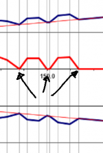
If L12 is long, the impact of any stuffing in that section is limited primarily to frequencies above 120 Hz or so and does not significantly affect passband sensitivity. Well, at least HornResp says so
The attached image shows the impact of stuffing L12 for the example TH given in the spreadsheet:
Attachments
Brian,1)The mouth is pictured as firing out the top (bottom!) because it's just easier to sim that way.
2)The mouth can be moved to facing the driver in the actual build, and any response changes should be minor. The builder can fiddle around with the shape of the mouth in the actual build as per the "Keystone" build.
3)If L12 is long, the impact of any stuffing in that section is limited primarily to frequencies above 120 Hz or so and does not significantly affect passband sensitivity. Well, at least HornResp says so
4)The 4015LF is quite different to the 3012LF, so hopefully my experience is different. In any case, I'm keeping the CR pretty low for this particular design, in the hope I don't run into that problem.
1) Top, bottom, whatever way you want to take it is OK- lets not get into those kinky details ..
2) "Fiddle about" reminds me of "Uncle Ernie" in the Who's rock opera ;^).
3) Give it a whirl, test, report back whether the sim and reality coincide.
4) The 4015LF is not much different to the 3012LF regarding the problem described.
Compare the Lab 12 Mms of 146 grams to the 3012LF at only 72.4- less than half.
The 4015LF has 139 grams Mms, still less than the Lab 12.
Then compare the ratio of Mms to Sd- the 3012LF has 62.5% Sd, but only 52% Mms.
Which do you think will "fold up like a cheap suit" first?
Have fun,
Good Luck!
Art
4) The 4015LF is not much different to the 3012LF regarding the problem described.
Compare the Lab 12 Mms of 146 grams to the 3012LF at only 72.4- less than half.
The 4015LF has 139 grams Mms, still less than the Lab 12.
Then compare the ratio of Mms to Sd- the 3012LF has 62.5% Sd, but only 52% Mms.
Which do you think will "fold up like a cheap suit" first?
A few things:
1. I'm already using the Dayton PA310 in a TH with a similar CR. Its Mms is near identical to the 3012LF. I'm changing out because it would occasionally hit Xmech when driven by my 1.2kW car subwoofer amplifier - not surprising, considering that HornResp predicted it to start exceeding its Xmax of 5mm with only 60W around 50 Hz
. 2. Remember that Mms is not only the weight of the cone, but the weight of the coil as well. The more copper wound around that coil, the higher Mms will be. the 4015 uses a 4" coil and has a 9mm Xmax, which suggests much more copper than the 3012 with its 3" coil and similar Xmax.
3. I tried the LAB12 in a number of 40 Hz TH designs. I couldn't get it to work without an overly underdamped response which I'm trying to avoid in my designs. It IS a nice driver, but seems a better fit for vented and FLH systems.
I've got a 3012LF on the way, to replace the PA310 driver in my POC3 TH. How it performs in that should give me a good idea on how it will perform in the design I'm still working on. I'm not going to start cutting wood until I sort out the cone compensation and "unused volume" things. So that might not get done until Xmas, LOL.
2. Remember that Mms is not only the weight of the cone, but the weight of the coil as well.
...and also the air load.
...and also the air load.
True, I'd forgotten about that! And that contribution would be greater as the size of the cone goes up.
I was looking online for a breakdown of what percentage of the driver's Mms is typically due to the voice-coil, cone and air-load, but I haven't found one yet. In summary though, I suspect that just looking at Mms alone only gives a very rough idea of how strong a driver's cone actually is. For example, two drivers may have identical Mms, but one may feature a longer, heavier coil, which means that its cone is likely lighter than the other driver's cone.
Like the work you have done here Brian!
Thanks!
I've attached an updated version of the workbook. There are still a few things that need to be cleaned up (like the "instructions" sheet), but it is usable at this point. It allows you to not only design a dual-expansion TH, but also to set different expansion ratios too. Then it's just a matter of hitting "Optimize" until all "Errors" column is all zeroes, at which point the HornResp data displayed in the workbook's "Design" sheet can be copied to HornResp for further analysis.
I've come across a few interesting things while messing around with it. For example, I tried expanding S1-S2 into the unused space in the center of the horn, but that actually made matters worse - apparently you can have a too-long S1-S2 section. Another thing is that, with a judicious choice of expansion ratios and driver position, you could negate the need to include any cone compensation, which would otherwise be required to avoid having a significant dip in the FR where the third major impedance spike occurs. For the example given, I assumed a front cone volume of 4 liters and zero cone compensation.
I've got a 3012LF on its way to me already. I can't wait to see how it performs in this particular design.
Attachments
Updated version attached. I did a bit of cleaning up, and now all of the routines on the "Designs" sheet work, e.g. showing how any required "cone compensation" can be included. I've also added a macro that can be used to create a HornResp import file with the information from the spreadsheet ("the "Export!" button). Of course you'll have to enter the driver data and some other information for the export file.
Attachments
I noted some years ago that a constriction in the flow path changes the predicted output from Hornresp.
Whereas an expansion seems to have almost no effect on the simmed output.
Brian's spreadsheet uses exclusively small expansions at the numerous corners. There are no constrictions to adversly affect the output.
I consider this an important attribute to Brian's designs.
Other software that introduces constrictions are likely to not perform as well.
I noted some years ago that a constriction in the flow path changes the predicted output from Hornresp.
Whereas an expansion seems to have almost no effect on the simmed output.
Brian's spreadsheet uses exclusively small expansions at the numerous corners. There are no constrictions to adversly affect the output.
I consider this an important attribute to Brian's designs.
Other software that introduces constrictions are likely to not perform as well.
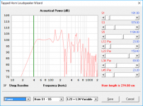
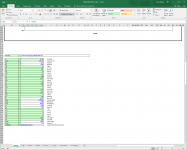
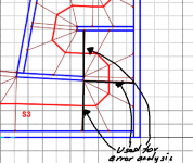
Hi Andrew, while my spreadsheet does ensure continuous expansion around a bend if it's used properly, the size of the expansion "bumps" on the horn expansion graph might be a bit misleading, and the actual expansion around the curves is a lot smoother than portrayed.
Here's why:
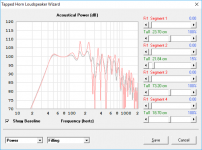
For analysis purposes, the spreadsheet calculates the CSA of the horn at points where it can be determined orthogonal to the path through the horn (illustrated by the red line in the image), and the difference between what the spreadsheet measures and what the CSA should be at that point in the horn's path is used for error-checking. However, using the sample points around a bend that were created using the "advanced centerline method" for this purpose is a bit of a challenge though, as the path is not orthogonal to the sample lines at those points, which means that the calculated CSA will be exaggerated. So while the CSA at these sample points are displayed in the graphs (hence the "bumps"), the spreadsheet ignores them in the error analysis.
Attachments
I've got a 3012LF on the way, to replace the PA310 driver in my POC3 TH. How it performs in that should give me a good idea on how it will perform in the design I'm still working on. I'm not going to start cutting wood until I sort out the cone compensation and "unused volume" things. So that might not get done until Xmas, LOL.
I received the 3012LF on Friday and today I had the opportunity to try it out in my POC3 TH. It seems to work well, and appears to be able to take a bit more from the amp before distortion becomes noticeable. The cone's suspension seems to be very different to that of the PA310 driver and unlike the PA310, it looks like the suspension might be stiffening up a bit before the driver's published Xmax is reached. Also, a few free-air tests with a LF tone at various voltage levels suggest that the 3012F can take a bit more voltage before distortion becomes apparent, and it's a 4-ohm driver (the PA310 is an 8 ohms).
The PA310 does have one advantage over the 3012LF however (apart from its much lower price) - motor noise is very low. As for the 3012LF, that iddy-biddy pole vent does not do it any favours, and the sound of air being squeezed through it is quite audible when playing back low frequency tones at high levels. This won't be a problem with the magnet structure being enclosed in a box as it would be if the 3012LF is used in a sealed or vented box, but in a TH that's another matter entirely. Still, it's only noticeable when playing back sine waves, and likely will be masked when music is being played through it.
Art, I did a little research on the Definimax 15", and it also seems to use a relatively small pole vent, considering that it uses a 4" coil and has a rated Xmax of 9mm. In fact, the pole vent for the PA310 looks like it might be larger, and that has a 3" coil with 5mm Xmax. I wonder if what you experienced with the Definimax was motor noise?
Brian,Art, I did a little research on the Definimax 15", and it also seems to use a relatively small pole vent, considering that it uses a 4" coil and has a rated Xmax of 9mm. In fact, the pole vent for the PA310 looks like it might be larger, and that has a 3" coil with 5mm Xmax. I wonder if what you experienced with the Definimax was motor noise?
The Keystone exit had to be reduced for the 15", and since the reduction of the exit was done at the top, the vent noise did not have a direct path out. Vent noise was not the problem, just plain harmonic distortion (plenty of odd order) with the 4015LF in the Keystone at high drive levels.
Art
A great example of more money does not always mean more better!
There may be a legitimate reason for Eminence using such a small pole vent for this driver. Maybe the mass of air between the vent and the dust cap that has to be squeezed through that small vent acts as some sort of "brake" to prevent the speaker from destroying itself if it sees a high-voltage low-frequency spike? Who knows...
The 3012LF's suspension is IMO better than that of the PA310. My PA310 driver is actually showing clear signs of cone sag at the moment, which I didn't expect for a speaker with a rated 72g Mms, but which also suggests that it also might not be a good match for any alignment that has it facing up or down (i.e. almost all TH designs, LOL). I might consider designing a cyclops TH variant for it, if I have the time. For comparison purposes, I recently had a look at my Infinity 122.7Ws that are currently in storage - 12" drivers with 262g Mmd, and absolutely no signs of any cone sag. Those feature Nomex spiders. I'm not sure what material the spiders are made of for the PA310 and the 3012LF, but they look like resin-impregnated cotton. I'm not sure about the 3012LF yet, but the PA310 could likely be significantly improved by simply switching to the use of a better spider.
All drivers are designed with trade-offs in tow. The smaller center vent allows a greater volume of metal in the pole. That can be advantageous to create the required magnetic flux density between the pole and the top plate. And in the emminence design it may have been advantageous to do so.
Using drivers in novel alignments has it's benefits and drawbacks. A stiffer spider would change the overall parameter balance in terms of Qtc and Vas, Fs.
Using drivers in novel alignments has it's benefits and drawbacks. A stiffer spider would change the overall parameter balance in terms of Qtc and Vas, Fs.
- Home
- Loudspeakers
- Subwoofers
- Spreadsheet for Folded Horn Layouts...