The proportionality of SPL to speed or acceleration is as I quoted Olsen.
If you insist that SPL in proportional to both cone velocity and acceleration,
the tie breaker would be which(velocity or acceleration) has the same phase behavior as SPL.
Since a woofer is just a mass-spring-damper system:
The phase of cone acceleration is zero relative to the driving signal(Force) above resonance and leads by 180 degrees below resonance
The phase of cone velocity leads the driving signal by 90 degrees below resonance and lags by 90 degrees above resonance.
Then only point where velocity is in phase with the drive signal is right at resonance.
Mic + dual trace oscilloscope show that SPL follows the phase of acceleration not velocity.
The basic physics is as I quoted from Olsen in post 24 of this thread. SPL is proportional to particle velocity, not acceleration.
In the special case of sinusoidal sound, or sound described in terms of its sinusoidal content, SPL is proportional to both velocity (speed) and acceleration. This is true simply because in the case of sinusoidal motion, velocity and acceleration, are proportional to each other.
The proportionality of SPL to speed or acceleration is as I quoted Olsen. It is proportional to speed (particle velocity) and to acceleration as so far as one wishes to describe sound in terms of sines and cosines.
Go way back to the original post and you will see that the question was about diaphragm behavior. That is then the context for this discussion.
IF you want to talk about sound fields rather than diaphragms, it appears you are right, but changing the context of a discussion just to be right is not exactly an accepted method for debate.
Whether talking about sound fields or diaphragms, Fouriers theorems hold true - there never has been a disconnect between sinusoids and nonsinusoids...
Yep, that's the Ron I remembered. Some things do stay the same.
Like,
...and,
"The relation between sound pressure and particle velocity is given by
P = pcu
where
P = sound pressure in dynes per square cm
p = density of air, in grams per square cm
c = velocity of sound, cm per second
u = particle velocity, in cm per second"
Like,
Go way back to the original post and you will see that the question was about diaphragm behavior. That is then the context for this discussion.
IF you want to talk about sound fields rather than diaphragms, it appears you are right, but changing the context of a discussion just to be right is not exactly an accepted method for debate.
Whether talking about sound fields or diaphragms, Fouriers theorems hold true - there never has been a disconnect between sinusoids and nonsinusoids...
...and,
"The relation between sound pressure and particle velocity is given by
P = pcu
where
P = sound pressure in dynes per square cm
p = density of air, in grams per square cm
c = velocity of sound, cm per second
u = particle velocity, in cm per second"
equation applies only in a terminated tube, enforcing plane wave conditions for a speaker driver
in application speaker drivers see varying acoustic Z with frequency because the waves are not constrained, vary by wavenumber interaction with diaphragm, box/baffle size, boundaries
in application speaker drivers see varying acoustic Z with frequency because the waves are not constrained, vary by wavenumber interaction with diaphragm, box/baffle size, boundaries
The basic physics is as I quoted from Olsen in post 24 of this thread. SPL is proportional to particle velocity, not acceleration.
As others have already mentioned, the basics physics you quoted is the relationship between the instantaneous pressure and particle velocity at a given point in space for a plane wave. The question was about the relationship between woofer cone motion(velocity/acceleration) and measured SPL.
Suppose I attached an accelerometer and a velocimeter to a woofer cone. I monitor the output of these sensors while playing test signals(any signal...music, clicks, pops, transients etc...no special case sine waves here
") ) and compare the sensor waveforms to the output of a microphone with an oscilloscope
) and compare the sensor waveforms to the output of a microphone with an oscilloscope Which sensor output will match the microphone response?
Having performed this experiment many times while working with servo feedback woofer systems, I can tell you that the accelerometer output is the one that matches the microphone response. To get the velocity sensor to match the output you need to tilt its response up +6dB/oct and shift its phase by 90 degrees.
Note that once you get to higher frequencies where wavelength is less than the cone diameter the radiation impedance flattens out and the directivity starts narrowing. The two effects cancel out so that the direct proportionality between acceleration and SPL still holds, but ONLY for on-axis and ONLY if the woofer cone is a perfectly rigid(no breakup modes) flat piston.
As others have already mentioned, the basics physics you quoted is the relationship between the instantaneous pressure and particle velocity at a given point in space for a plane wave. The question was about the relationship between woofer cone motion(velocity/acceleration) and measured SPL.
Suppose I attached an accelerometer and a velocimeter to a woofer cone. I monitor the output of these sensors while playing test signals(any signal...music, clicks, pops, transients etc...no special case sine waves here
Which sensor output will match the microphone response?
Having performed this experiment many times while working with servo feedback woofer systems, I can tell you that the accelerometer output is the one that matches the microphone response. To get the velocity sensor to match the output you need to tilt its response up +6dB/oct and shift its phase by 90 degrees.
Note that once you get to higher frequencies where wavelength is less than the cone diameter the radiation impedance flattens out and the directivity starts narrowing. The two effects cancel out so that the direct proportionality between acceleration and SPL still holds, but ONLY for on-axis and ONLY if the woofer cone is a perfectly rigid(no breakup modes) flat piston.
So are you saying that in a plane wave the SPL is proportional to velocity but that in a wave form generated by a transducer the basic physics changes to become proportional to acceleration?
So are you saying that in a plane wave the SPL is proportional to velocity but that in a wave form generated by a transducer the basic physics changes to become proportional to acceleration?
No. Basic physics stay the same, you just need to be careful using formulas where they don't apply.
If you measure particle velocity(with a ribbon microphone) and pressure(with an omni electret microphone) at a point far enough away from a woofer that the wave front is essential that of a plane wave, the proportionality will hold and both microphones will show the same response. This does not mean, however that this measured response is proportional to the woofer cone velocity.
If you move close to a woofer(a good approximation of an omni source) with the same two microphones where the wave front is curved and "stretching out", the ribbon microphone will show progressively higher output than the electret pressure microphone at low frequency. Near an omni source, the velocity of the air particles isn't just moving away/towards the source but includes a component of velocity perpendicular to "on-axis". This is the "stretching" component of the velocity.
Perhaps it will help to consider that the cone only has the away/towards component of velocity and the air particles adjacent to the cone are not only moving away/toward but also moving to the side as they rush out of the way of the cone moving to displace them. A 2D visual might be water motion as you move a canoe paddle back and forth. This sideways motion of the air particles is also what give rise to the falling radiation resistance which ties in with why it is constant acceleration that gives flat response.
Now, fire the same woofer into a terminated tube( as jcx mentioned) the size of the woofer cone and no stretching takes place, particle velocity is directly away/towards the cone, radiation impedance is constant = rho x c, plane waves are generated and pressure is proportional to velocity anywhere in the tube. Further more the pressure measured in the tube would be proportional to the cone velocity.
Last edited:
Is Sound Pressure Level generated by a transducer proportional to speed of the cone or acceleration of the cone.
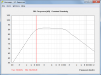
Attachment 1 - On-axis sound pressure level 1 metre from driver diaphragm. Driver mounted in an infinite baffle.
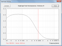
Attachment 2 - Peak velocity of diaphragm.
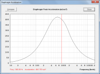
Attachment 3 - Peak acceleration of diaphragm.
Attachments
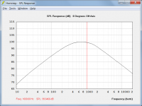
Attachment 1 - On-axis sound pressure level 1 metre from driver diaphragm. Driver mounted in an infinite baffle.
If you plot 20*LOG of your acceleration data it will match response trend of SPL plot (20*LOG of Pressure/Pref).
I performed a few hand calcs to check, taking 20*LOG of data from the acceleration plot and the results match the HF and LF roll off slopes shown in the SPL plot.
Hmmm...speaking of roll off slopes...the LF roll off rate is 6dB/octave.
When you said infinite baffle I assumed you meant sealed box, but that would indicate a 12dB/octave roll off rate.
Just curious, what exactly was being modeled?
Hmmm...speaking of roll off slopes...the LF roll off rate is 6dB/octave.
When you said infinite baffle I assumed you meant sealed box, but that would indicate a 12dB/octave roll off rate.
Just curious, what exactly was being modeled?
The simulation was for a driver in an infinite baffle - as stated. The SPL response chart posted showed the output from one side of the driver. Each side of the driver diaphragm radiates into a solid angle of 2 pi steradians (half space). Note that this is not the same as a driver suspended in free space radiating into 4 pi steradians, in which case the front and rear outputs cancel due to the 180 degree phase difference.
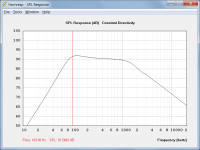
The attached screenprint compares the same driver in a sealed box enclosure (black trace) against the previously posted infinite baffle result (grey trace).
Attachments
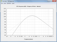
The attached screenprint compares the same driver in a sealed box enclosure (black trace) against the previously posted infinite baffle result (grey trace).
Aaah...ok.
Looks like your simulations were run with a driver having unusually low Qts. Perhaps around 0.10?
Most woofers designed to be used as direct radiators have Qts>0.3 and you will see the response revert to the 12dB slope on the low end even in the infinite baffle case.
Attachments
Looks like your simulations were run with a driver having unusually low Qts. Perhaps around 0.10?
For the purpose of the SPL / velocity / acceleration / exercise I simply used the Hornresp default driver, Qts = 0.13.
Most woofers designed to be used as direct radiators have Qts>0.3 and you will see the response revert to the 12dB slope on the low end even in the infinite baffle case.
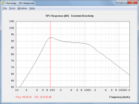
Attachment 1 - Driver in infinite baffle with fs = 100 Hz and Qts = 0.71
Attachment 2 - Driver in infinite baffle with fs = 100 Hz and Qts = 1.00
Attachment 3 - Driver in infinite baffle with fs = 100 Hz and Qts = 1.41
Attachments
Hi, this is my first post on this forum! (I've been lurking for a few weeks now, and, as a result, I'm in the process of starting a little open-baffle project - but that's another story...)
I have a problem, and realise that some of the expertise shown in this thread may be able to help me. The problem is one of incessant low-frequency noise in my home (due to nearby factory???). To combat this, I thought I'd try a bit of noise cancellation. This would involve a mass-added woofer (to minimise phase shift at the frequencies of interest), and a capacitor mic (from a cheap dB meter).
Since this would be a feedback system, it's important to have an idea of open-loop phase response. With this in mind, my question would be: what would the phase relationship be between speaker (in closed box) driving voltage and microphone output? Microphone would be placed close to the speaker, and the speaker should look pretty much pure resistive at the frequencies of interest.
I hope the above isn't taken as going off on a tangent too much - as I say, the expertise is here in this thread, and the question does seem fairly relevant anyway.
Feedback around loudspeakers is an interesting and difficult topic of its own, but low frequency noise cancelling has a more difficult component. Within a room the distribution of tones varies widely, in three dimensions (plus time). Try to fix things for one point and you make it worse in many others, and vice versa. Headphones with local mic can work though.
All good fortune,
Chris
All good fortune,
Chris
Yes, certainly a tricky subject. Just to be more specific, the frequency range will be restricted to about 20-50Hz (as a first try), and the idea is to reduce the noise over a small area, in a small room (I realise that anything more ambitious would be outside the realms of possibility). The driver will no doubt end up with a very heavy cone, to get resonance down to few Hz.
Headphones aren't really an option, owing to comfort issues. I do need to have a fairly clear and accurate picture of phase response, because I'll be designing this by "dead reckoning" as I unfortunately don't have any test equipment other than a multimeter.
Headphones aren't really an option, owing to comfort issues. I do need to have a fairly clear and accurate picture of phase response, because I'll be designing this by "dead reckoning" as I unfortunately don't have any test equipment other than a multimeter.
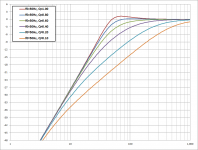
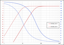
... what would the phase relationship be between speaker (in closed box) driving voltage and microphone output? Microphone would be placed close to the speaker, and the speaker should look pretty much pure resistive at the frequencies of interest.
Attached is a plot show relative response(red curves) and phase (blue curves) for a critically damped closed box woofer. Phase shifts from 0deg(in phase) above resonance to 180deg(out of phase) below resonance. With resonance set at a typical 50hz(solid lined), you can see that you would need to include some sort of phase compensation to keep a feedback loop stable when a useful amount of open loop gain was used. If you added enough mass to the woofer to push resonance down to 10Hz(dotted lines) you may get away with minimal phase compensation. However, be aware that you would also need to consider the phase response of your microphone and any other AC coupled circuits in your feedback loop to avoid instability above or below your bandwidth of interest.
It is certainly possible to reduce LF noise at your listening position with a noise cancelling woofer set right next to you....the frequency range will be restricted to about 20-50Hz (as a first try), and the idea is to reduce the noise over a small area, in a small room
However this will cancel out not only the unwanted noise, but also any bass content in the music you are listening to on your open-baffle speakers.
I do need to have a fairly clear and accurate picture of phase response, because I'll be designing this by "dead reckoning" as I unfortunately don't have any test equipment other than a multimeter.
Personally I would not consider trying to design a noise cancelling woofer circuit without equipment to measure open loop gain and phase.
As mentioned above, you will need to know the phase reponse of the entire open loop signal path, not just the woofer portion. You might take a look at one of th MFB(Motional FeedBack) threads to get an idea of what is involved. Basically it is the same thing as what you are wanting to do, but the sensor is an accelerometer rather than a microphone, and the unwanted signal is distortion instead of noise.
http://www.diyaudio.com/forums/subwoofers/239941-analog-servo-sub.html#post3576660
Measuring open loop gain/phase: http://www.diyaudio.com/forums/subwoofers/239941-analog-servo-sub-2.html#post3580077
Plot of open loop measurement: http://www.diyaudio.com/forums/subwoofers/239941-analog-servo-sub-6.html#post3590105
Attachments
Last edited:
- Status
- This old topic is closed. If you want to reopen this topic, contact a moderator using the "Report Post" button.
- Home
- Loudspeakers
- Multi-Way
- SPL function of speed or acceleration