So, to find the interwinding capacitance for a simple two-winding transformer model, could I apply a known amplitude and frequency of RF to the primary of a real transformer (to be modeled), measure how much of that RF appears across the secondary, and then put an RF source (with the same amplitude and frequency) on the model's primary and adjust the model's interwinding C value until I get the same RF level across the model's secondary?
Just a wild guess. Otherwise, how?
- Tom Gootee
http://www.fullnet.com/~tomg/index.html
Just a wild guess. Otherwise, how?
- Tom Gootee
http://www.fullnet.com/~tomg/index.html
Or how about varying the primary's excitation frequency and looking for a resonant peak across the secondary? Would it then be possible to estimate the interwinding capacitance, if the primary and secondary (and leakage) inductances, and the resistances, are known?
By the way, does anyone have a feel for whether or not the INTRA-widing capacitances might be important to model? i.e. the capacitance seen between the two primary leads, and the capacitance seen between the two secondary leads?
I don't yet have much of a concept of the relative magnitudes of any of these capacitances. But it seems like they might be important, when looking at any types of high-frequency effects in any transformer-related circuits. But, if not, usually, then that would be very nice to know, right about now.
- Tom Gootee
http://www.fullnet.com/~tomg/index.html
Firstly, I am quite envious of the learned work done regarding equivalent models of UL output transformers. To my mind getting a fairly exact model, especially regarding distributed capacitances, must be quite a task. Up to now I have chickened out and done the reponse with tubes and transformer in situ. The hf side is not usually a problem and one can take phase shifts into account by tailoring the final response. But just my laziness!
Tom,
I have found that quite often the h.f. limit is governed more by the capacitance (interwinding plus tube) than the leakage reactance. There is an unbalance in a design where the leakage is low enough to take one to quite >100KHz, but the capacitance starts cutting after 30KHz. In this sense I am limiting my sectionalising to 3 - 4 secondaries and/or using some extra insulation thickness between pri-sec. sections. In a 100W C-core transformer I tried to do as good a job as possible of guestimating the equivalent internal C, and got a figure of around 1,2nF equivalent at the tube anodes. This was with 4 secondaries, not a split bobbin.
I have done a little more research and have found that, for a simple two-winding transformer, the interwinding capacitance can be measured by shorting both windings and measuring the capacitance between them. Then, each winding can be shorted, one at a time, and the intrawinding capacitance of each one in parallel with the interwinding capacitance can be measured. Knowing the interwinding capacitance, each intrawinding capacitance can then be calculated.
But I'm still not sure what the best capacitance measurement methods would be, in those cases.
- Tom Gootee
http://www.fullnet.com/~tomg/index.html
But I'm still not sure what the best capacitance measurement methods would be, in those cases.
- Tom Gootee
http://www.fullnet.com/~tomg/index.html
Maybe to model those UL (UltraLinear) transformers well, one would need to resort to using the techniques similar to those described on these pages:
http://www.d4magnetics.com/page8/page8.html
The models are derived from the geometric and materials properties of the core and windings.
This looks quite interesting, too:
http://www.upmdie.upm.es/investigacion/ficheros/APEC_1997.pdf
- Tom Gootee
http://www.fullnet.com/~tomg/index.html
http://www.d4magnetics.com/page8/page8.html
The models are derived from the geometric and materials properties of the core and windings.
This looks quite interesting, too:
http://www.upmdie.upm.es/investigacion/ficheros/APEC_1997.pdf
- Tom Gootee
http://www.fullnet.com/~tomg/index.html
This author posted a new and improved spreadsheet at:Here are just two examples of how I do output transformers. They should work with any Spice variant as far as I know, I personally use LTSpice. I do have a vague recollection however that some spices wont allow more than 2 inductances on a K statement, so you have to put a seperate line for each pair of inductances.
Complex example, ie PP, UL, and multiple output taps.
.SUBCKT 1650R P1 Sg1 B Sg2 P2 O16 O8 O4 Com
* Push Pull transformer, with Ultralinear taps at 40%
* 5000 to 16 ohms, with 8 ohm and 4 ohm taps, 3db 15 to 60Khz
* Hammond 1650R
*
LP1 1 2 2.409088925H ; PRIMARY
LS1 2 B 1.070706189H ; primary, scrren grid tap portion
LS2 B 3 1.070706189H
LP2 3 4 2.409088925H
LA1 5 6 0.007348166H ; SPEAKER SECONDARY
LA2 6 7 0.003674083H
LA3 7 Com 0.021414124H
KALL LP1 LS1 LS2 LP2 LA1 LA2 LA3 0.999199994;
RP1 P1 1 30.0
RP2 Sg1 2 15.0
RP3 Sg2 3 15.0
RP4 P2 4 30.0
RS1 O16 5 0.1
RS2 O8 6 0.1
RS3 O4 7 0.1
.ENDS 1650R
P1 and P2 are the plate connections, B is the B+ connection, Sg1 and Sg2 screen grid connections, and O16, O8 and O4 the 16, 8 and 4 ohm outputs, and Com the common secondary terminal
Simplest example, ie SE, single output.
.SUBCKT 5KSE P1 P2 Sp1 Sp2
* Single ended audio transformer
* 5k to 8 ohm, 10 to 40KHz
*
LP1 1 P2 40.26021568H ; PRIMARY
LSA 2 Sp2 0.064416345H ; SPEAKER SECONDARY
KALL LP1 LSA 0.999499875 ;
RP1 P1 1 56
RS Sp1 2 .1
.ENDS
P1 and P2 are the primary ie plate connections, and Sp1 and Sp2 the secondary ie speaker connections.
When loaded by the specified input and output resistances they give the specified frequency response. They include winding resistance so you get the expected voltage drops. These are purely linear models and so do not give any distortion. So they are not realistic in that regard, but the fact that the taps "work right", ie the ultralinear acts as it should, and you can put 4 ohms on the 4 ohm tap or 8 ohms on the 8 ohm tap and get the right results make them very useful in my opinion. The frequency response may not have all the little quirks of the real transformer, but it is reasonable, not DC to infinity or anything like that.
I use the attached spreadsheet to derive the model parameters. The values given for the various transformers listed are taken from various data sheets and websites and so on. Many of the dc resistances are just pure guesses on my part. I make no claim that the models will match the real transformer, only that the model will have the frequencey response and impedance ratio that the spec sheet claims for the real transformer.
The spreadsheet is just something I whipped up for myself, so it is not particularly user friendly perhaps, but it should be fairly easy to use. Just input nominal source impedance, output impedance, winding resistances and upper and lower 3dB frequencies, and then in the rightmost columns you will get KA, LP and LS for SE types, or KA, LP1, LP2, and LS2 for PP types. Paste those values into the spice model. If you want multiple output taps then take the value for LS and paste it into cell A7 on sheet 2, set the tap impedances as required ( default is 4, 8, and 16) and then see the values for LA1, LA2 and LA3. Paste these into the spice model.
http://www.diyaudio.com/forums/tubes-valves/181578-spice-transformer-model-spreadsheet.html
. . .
I don't yet have much of a concept of the relative magnitudes of any of these capacitances. But it seems like they might be important, when looking at any types of high-frequency effects in any transformer-related circuits. But, if not, usually, then that would be very nice to know, right about now . . .
All you always wanted to know about OPTs is in RDH4 chapter 5 !
In 5.3(v) you'll find how to calculate winding capacitances.
They have multiple sources (inter winding and inter layers) and always produce dips or peaks accompanied by suddent phase shifts that are highly undesirable !
The larger the OPT, the higher the parasitic capacitances
")
Yves.
Interesting application note on determining the intra winding capacitanceOr how about varying the primary's excitation frequency and looking for a resonant peak across the secondary? Would it then be possible to estimate the interwinding capacitance, if the primary and secondary (and leakage) inductances, and the resistances, are known?
By the way, does anyone have a feel for whether or not the INTRA-widing capacitances might be important to model? i.e. the capacitance seen between the two primary leads, and the capacitance seen between the two secondary leads?
I don't yet have much of a concept of the relative magnitudes of any of these capacitances. But it seems like they might be important, when looking at any types of high-frequency effects in any transformer-related circuits. But, if not, usually, then that would be very nice to know, right about now.
- Tom Gootee
http://www.omicron-lab.com/fileadmin/assets/application_notes/AP_Note_Transformer_V_1_0c.pdf
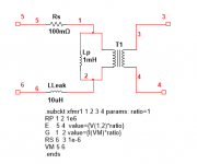
Going to repeat here what I posted on the vacuum tube spice page. This is cobbled from Christophe Basso's book on switch mode power supplies. Add the parasitic elements to your heart's content. Multiple sections can be added in series and parallel to derive a UL transformer of your choosing by changing the parameter "ratio" in the spice model:
Attachments
32 section Hammond 1628SEA's UL model
I have attached my implementation of a 32 section distributed lumped element LTSpice model of the Hammond 1628SEA OPT.
This post is not meant to be complete or scientific, but please let me know if I am on the right or wrong track.
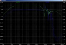
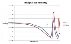
I was interested in attempting to model the primary-secondary capacitance and in particular the amplitude and phase relationship between the plate and UL taps of the primary at higher frequencies.
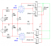
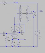
I had bench built a simple SE 6CA7 UL stage using the Hammond but had seen oscillations when connected in UL mode, but not in triode or pentode mode. Testing the OPT showed that around 88kHz there was a 180 deg phase shift between UL and plate connections, with V(UL) becoming larger than V(plate) (and leading to positive feedback to g2 I guess) so I wanted to see if this could be modelled in Spice.
The model is simple in that the primary and secondary are split into 32 mutually coupled inductors with the primary-secondary capacitance distributed as 33 discrete capacitors between the respective primary and secondary inductor nodes. In addition I have included dc resistance, primary winding capacitance, leakage reactance (manifesting as the coupling coefficient) and a series cap-resistor to attempt to model HF hysteresis losses….. (not very scientific I know…)
I found that the 32 section was an improvement on a 16 and 8 section model because the model performance in simulation was less sensitive to the input capacitance values, otherwise you end up with oscillations in the simulated circuit that are not there in real life.
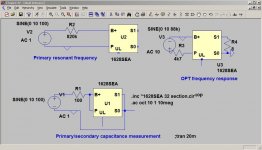
To get the parameters not listed by the manufacturer I had only a LRC meter, oscilloscope and signal gen at hand, so used 3 small test circuits to measure parameters, then simulate the test circuit and compare results.
Extract of the sub circuit model:
************************************************************************************************************
* Generic UL SE OPT
* Input parameters:
* LP = manufacturer large signal primary inductance
* RP = manufacturer primary load impedance
* RS = manufacturer secondary load impedance
* RSP = measured primary series winding resistance
* RSS = measured secondary series winding resistance
* LPL = measured leakage inductance at primary with secondary short circuit. Used to calculate coupling coeffcient.
* CPS = measured primary/secondary inter-winding capacitance
* CP = estimated parallel primary winding capacitance - this is distributed accross the primary inductances - can create instability or too low resonant frequency;
* CPP = estimated primary winding capacitance Chose with CPS to get as close a match to resonant freq. Used to try simulate high freq core losses
* RHL = load resistor used in series with CPP for hysterisis losses simulation; for max loss RHL = output tube plate resistance;
* RPP = primary parallel resistance chose to match input level with open circuit secondary at resonance
* k = UL factor (winding fraction from B+)
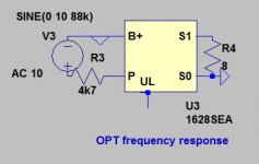
.SUBCKT 1628SEA 1 2 3 4 5; P B+ S0 S1 UL;
*
X1 1 2 3 4 5 OPT LP=45 RP=5000 RS = 8 RSP = 178 RSS = 0.5 LPL = 25.8m CPS = 3.5n CP=0.5p CPP=1n RHL= 1000 k = 0.4 RPP=546k
.ends
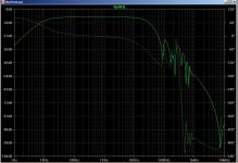
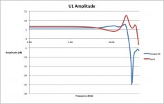
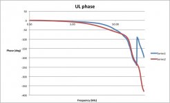
This model does simulate the OPT performance reasonably well and shows the UL plate relative amplitude and phase change in a satisfactory way, although the frequencies at which this resonance occurs differs slightly in real life. Installing the model as a subcircuit in Spice correctly predicts the oscillation I observed at the bench, and allowed me to eliminate this with a 470pF capacitor between g2 and plate.
I have attached the simulated transformer frequency response for the plate connection (green) and the UL connection (blue) which shows the amplitude and phase change, very similar to what I measured.
It would be interesting to try a few other OPT’s (I only have the Hammond) to see how useful/adaptable this method is.
Any comments are appreciated.
I have attached my implementation of a 32 section distributed lumped element LTSpice model of the Hammond 1628SEA OPT.
This post is not meant to be complete or scientific, but please let me know if I am on the right or wrong track.
I was interested in attempting to model the primary-secondary capacitance and in particular the amplitude and phase relationship between the plate and UL taps of the primary at higher frequencies.
I had bench built a simple SE 6CA7 UL stage using the Hammond but had seen oscillations when connected in UL mode, but not in triode or pentode mode. Testing the OPT showed that around 88kHz there was a 180 deg phase shift between UL and plate connections, with V(UL) becoming larger than V(plate) (and leading to positive feedback to g2 I guess) so I wanted to see if this could be modelled in Spice.
The model is simple in that the primary and secondary are split into 32 mutually coupled inductors with the primary-secondary capacitance distributed as 33 discrete capacitors between the respective primary and secondary inductor nodes. In addition I have included dc resistance, primary winding capacitance, leakage reactance (manifesting as the coupling coefficient) and a series cap-resistor to attempt to model HF hysteresis losses….. (not very scientific I know…)
I found that the 32 section was an improvement on a 16 and 8 section model because the model performance in simulation was less sensitive to the input capacitance values, otherwise you end up with oscillations in the simulated circuit that are not there in real life.
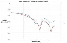
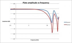
To get the parameters not listed by the manufacturer I had only a LRC meter, oscilloscope and signal gen at hand, so used 3 small test circuits to measure parameters, then simulate the test circuit and compare results.
Extract of the sub circuit model:
************************************************************************************************************
* Generic UL SE OPT
* Input parameters:
* LP = manufacturer large signal primary inductance
* RP = manufacturer primary load impedance
* RS = manufacturer secondary load impedance
* RSP = measured primary series winding resistance
* RSS = measured secondary series winding resistance
* LPL = measured leakage inductance at primary with secondary short circuit. Used to calculate coupling coeffcient.
* CPS = measured primary/secondary inter-winding capacitance
* CP = estimated parallel primary winding capacitance - this is distributed accross the primary inductances - can create instability or too low resonant frequency;
* CPP = estimated primary winding capacitance Chose with CPS to get as close a match to resonant freq. Used to try simulate high freq core losses
* RHL = load resistor used in series with CPP for hysterisis losses simulation; for max loss RHL = output tube plate resistance;
* RPP = primary parallel resistance chose to match input level with open circuit secondary at resonance
* k = UL factor (winding fraction from B+)
.SUBCKT 1628SEA 1 2 3 4 5; P B+ S0 S1 UL;
*
X1 1 2 3 4 5 OPT LP=45 RP=5000 RS = 8 RSP = 178 RSS = 0.5 LPL = 25.8m CPS = 3.5n CP=0.5p CPP=1n RHL= 1000 k = 0.4 RPP=546k
.ends
This model does simulate the OPT performance reasonably well and shows the UL plate relative amplitude and phase change in a satisfactory way, although the frequencies at which this resonance occurs differs slightly in real life. Installing the model as a subcircuit in Spice correctly predicts the oscillation I observed at the bench, and allowed me to eliminate this with a 470pF capacitor between g2 and plate.
I have attached the simulated transformer frequency response for the plate connection (green) and the UL connection (blue) which shows the amplitude and phase change, very similar to what I measured.
It would be interesting to try a few other OPT’s (I only have the Hammond) to see how useful/adaptable this method is.
Any comments are appreciated.
Attachments
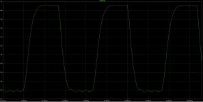
Yes I did measure... I have attached a few results with the Spice comparison
Attachments
I agree it is a bit like taking a sledgehammer to a crack a nut and does slow down the simulation somewhat. It is not clever but simply an interpretation of the physical that lets Spice do the maths for you. For a small SE type circuit the wait is not too long, but long transient analysis will take time.
It has been a useful educational exercise for me and it did correctly predict the oscillation with UL connection,and confirmed the corrective measure would work without having to stick my hands into HV!
If you know the physical winding arrangement you can construct any model that represents the OPT. I have now added the (not connected) 16 Ohm tap and it is interesting how that changes the resonant frequencies.
All good fun. Time to now build the real thing.
Attachments
- Status
- This old topic is closed. If you want to reopen this topic, contact a moderator using the "Report Post" button.
- Home
- Amplifiers
- Tubes / Valves
- spice model for UL output transformer?