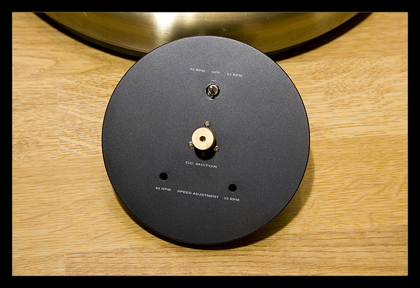
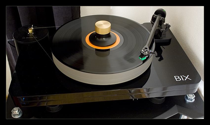
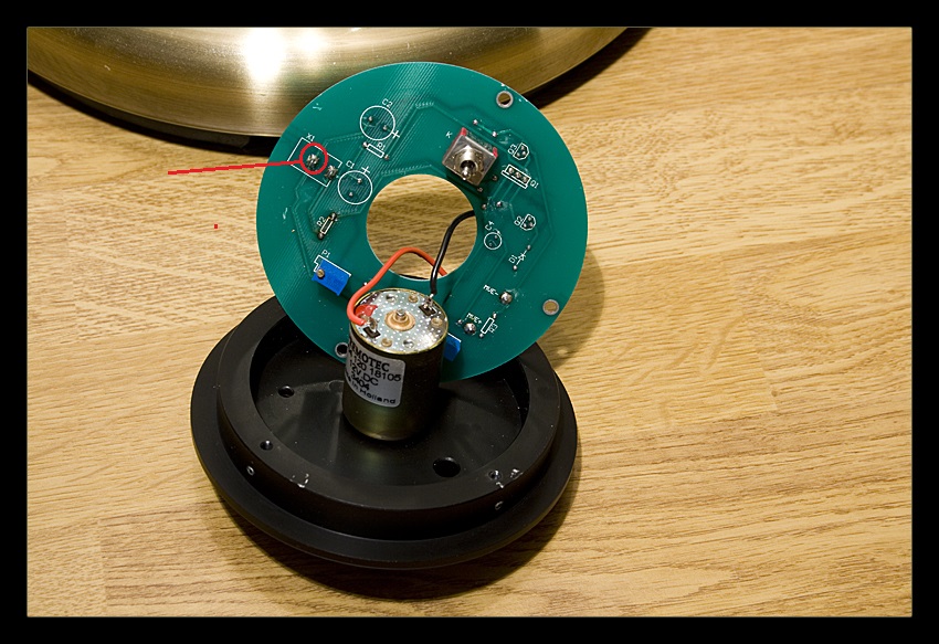
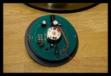
Hello fellow DIY'ers. I have a BIX turntable were the speed is impossible to keep at 33 1/3. It seems like the speed is always increasing. Anyone have any experience with this problem? I'm suspecting the motor to be the problem.
- Motor is a Premotec 9904 120 18105.

- Motor is a Premotec 9904 120 18105.
Attachments


It's a DC motor so it is either a steadily increasing voltage as it warms up or the lube in the motor and or platter spindle is a bit gummy but loosens up as it warms up.
It looks like you can operate the motor out of its housing. If you have a digital multimeter you can measure the DC at the motor leads when cold. Compare it to the voltage after the unit is plenty warmed up to see if it has increased. If the voltage is increasing I'd look to the voltage regulator or the screw speed adjustment pots.
I'd look to the belt if the speed was consistent but incorrect. Or if there was some flutter or wow. Not likely with that size platter but you never know.
Good luck.
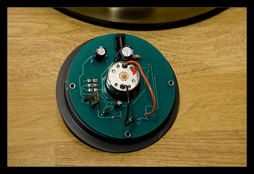
This motor is running open loop, there is no feedback control of motor speed and even things like the motor windings heating up during initial operation are going to result in speed drift.
A potential alternative that might allow you to salvage the existing motor set up would be to design a simple servo using a wheatstone bridge topology..
Here is what I was referring to specifically. Why TI changes their internal link structure and makes things impossible to find I'll never know, but here it is for now:
http://www.ti.com/lit/an/sboa043/sboa043.pdf
Kevinkr makes an excellent point. Without a servo control the motor speed will slowly drift as it warms up. Nothing to fix as it is design. You can upgrade it as kevinkr suggests or get a strobe so that you can adjust the speed every time you change an album.
Cudo's to kevin.
Cudo's to kevin.
Thanks for the replies guys. I've been working a lot lately, so my turntable have been completly forgotten. Used the weekend to assembly a little shopping list, so maybe I can start up this project again ") Ordered myself a Okki Nokki this morning just to give myself a reason to continue with this project.
Ordered myself a Okki Nokki this morning just to give myself a reason to continue with this project.
If this works, the next project will be modifying the Rega arm.
Ordered myself a Okki Nokki this morning just to give myself a reason to continue with this project.If this works, the next project will be modifying the Rega arm.
Here is the datasheet for the OPamp. Can't figure out exactly where to get the control voltage (V -In & V +In).
https://www1.elfa.se/data1/wwwroot/assets/datasheets/elOPA548_e.pdf
PS. I don't have any real experience with electronics at this level, but this is good practice
https://www1.elfa.se/data1/wwwroot/assets/datasheets/elOPA548_e.pdf
PS. I don't have any real experience with electronics at this level, but this is good practice
Your control voltage is just taken from the wiper of a pot wired across a stable voltage. In other words a variable DC voltage but one that is stable once set.
(the type of speed control in Kevin's link was really common on cassette deck motors. It senses the back EMF from the motor which changes under load. You could even rip the back off an old motor and probably use the PCB. You would have to alter and select the "sense" resistor to suit your motor. If the value is wrong then the motor will either speed up under load or reduce speed depending on the resistor error)
(the type of speed control in Kevin's link was really common on cassette deck motors. It senses the back EMF from the motor which changes under load. You could even rip the back off an old motor and probably use the PCB. You would have to alter and select the "sense" resistor to suit your motor. If the value is wrong then the motor will either speed up under load or reduce speed depending on the resistor error)


You need to see how the original board is configured.
Looking closely at the board and it looks as though it might be a circuit similar to the ones I mentioned in cassette motors etc. Is that resistor near the motor orange wire a low value such as 4.7 ohm.
(I thought you were making a new regulator with an power opamp)
Looking closely at the board and it looks as though it might be a circuit similar to the ones I mentioned in cassette motors etc. Is that resistor near the motor orange wire a low value such as 4.7 ohm.
(I thought you were making a new regulator with an power opamp
)
Not if its 10k.
Unless the circuit is accurately drawn out its all guesswork but I find it hard to believe a motor for such a critical application would run without any feedback control at all.
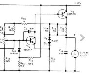
This is an example of a typical circuit. The three 10 ohms in parallel (equivalent to 3.3ohm) is selected to suit the motor and approximates (if I remember correctly) to the resistance of the motor winding. Get the value spot on and the motor speed is accurately maintained under varying load conditions.
Unless the circuit is accurately drawn out its all guesswork but I find it hard to believe a motor for such a critical application would run without any feedback control at all.
This is an example of a typical circuit. The three 10 ohms in parallel (equivalent to 3.3ohm) is selected to suit the motor and approximates (if I remember correctly) to the resistance of the motor winding. Get the value spot on and the motor speed is accurately maintained under varying load conditions.
Attachments
- Status
- This old topic is closed. If you want to reopen this topic, contact a moderator using the "Report Post" button.
- Home
- Source & Line
- Analogue Source
- Speed problems (BIX)