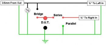
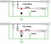
Here are two examples of modes. I haven't tried them yet, but I used Eric's and Claudio's schematics in my planning so I hope this is accurate.
I do not show anything in the way of using the voltage divider or the bypass output (1/4" T-S jack), which I guess could also be used as an input if necessary.
Edit: clarification, jacks are defined relative to the sound card. So Out actually means Sound Card Out not jig output. It should be clear from the drawing, but I don't want to confuse anyone stumbling upon this.
Attachments
Okay, I've spent the better part of the evening calibrating this thing, and I'm at a loss.
I can get the amplifier pulse and channel separation calibrations done. It gives me reasonable values for soundcard impedance and capacitance. And it calibrates the jig to almost exactly the reference resistor value.
So all that being said, it can't measure components accurately at all.
It identifies resistors and inductors as capacitors, and for capacitors, it doesn't come close to getting the value right. It seems to have repeatability, though.
I've tried different sampling rates and multiple MLS cycles for a better signal to noise measurement. Still nothing.
The jig checks out, though.
My friend seems to thing the M-Audio MobilePre might have a capacitive coupling on the input stage to take off the phantom power from the mic. This capacitor might be screwing up the measurements. I've searched for Speaker Workshop and MobilePre and I seem to be the first person trying this.
A lot of people have been trying SoundEasy and the MobilePre with mixed results and this might be why.
Ugh, if I can't get a resistor to measure right, there's no way I'll believe an impedance plot for a driver that I measure.
Advice appreciated. Until then I'll keep cranking at it.
Thanks.
HELP
Okay, consider this a HELP flag.
I've done everything twice. I even built Claudio's jig as well and can't get comonent measurements to work.
Steps I took:
Built Jig(s)
Hooked up in pure loop mode (L-L, R-R) and tested using RMAA. Not the best numbers, but good and it was getting a signal, so I moved on.
Hooked it up in SW loop mode (L-R&L), no resistors.
Made a 1k sine wave. Did record, check levels, and repeat. Got good results at 25k w/ no clipping.
Did amplifier calibration (the soundcard compensation)
Did channel difference calibration. I had to adjust the interchannel delay to get flat phase up high (+23 us).
Soundcard calibration:
Hooked up 10k resistor to the jig. Ran the SC impedance test.
100kOhms resistance, 320pF capacitance
Jig Calibration:
Hooked up 10 Ohm resistor and ran the test with a 5.1 Ohm and 20 Ohm test resistors. It came back with:
9.8 Ohms for the reference resistor
0.15 Ohms for the series resistance
So far all the figures look in line with what I expected.
Then I hooked up a 4 Ohm resistor to check. It came back as a Capacitor of value 41 uF and resistance of 5.8 Ohms!!!
I tried inductors and capacitors and none are even close. Other resistors are way off as well. Even the actual ones I used to calibrate it with!
Results are the same with both jigs, although the Claudio jig has a lot less resistance, so I'm probably going to stick with it over the one I made. Oh well.
Sound card is a M-Audio MobilePre. By spec it's listed as a 16bit, 44.1kHz card, but RMAA says it will handle 96kHz, 32-bit. All tests were done at 16-bit, 44.1kHz.
Sample size was 256k, MLS warmup was 100 cycles.
I applied for an account over on the Audua forums, but it hasn't been activated yet.
Any ideas? I'm at a loss now. The current theory is that this sound card is not up to the task, but I'd like to exhaust all other options before giving up on it.
Thanks,
AC
I get accurate capacitor and resistor ratings.
I only use the sound card for my impedance measurements. I get accurate resistor and capacitor readings. I'm not certain my inductor readings are accurate, but at least SW correctly identifies what it is testing.
Make sure you sound card is set to equal input/output. It is better to have the volume lower - not higher. I find higher volumes lead to noisier impedance graphs.
My volume is set to only 9K peak to peak (sine wave 1KHz to verify). I set the wave output to 100% via SW and the volume is set to only about 1/4 (to get the 9K level).
I recommend you do a free air impedance graph and post that. you should be able to get it relatively noise free. The reason I think this will work (or could highlight other problems) is you are able to accurately measure you ref resistors.
FYI, I use wire-wound resistors. My values are approx 8.25 ohms for the reference, and I used 15.9 and approx 3.7 as my calibration resistors. I don't think quality of resistors will matter much.
So - lower the sound card volume and don't use an amplifier for your impedance tests and let us know how it goes.
I remember getting way out of spec values too. We'll get you there") .
.
Jay and Claudio - if you are reading - any help appreciated.
PS: I also requested a SW forum account but don't think the moderators are active at the moment.
Cheers,
Davd.
I only use the sound card for my impedance measurements. I get accurate resistor and capacitor readings. I'm not certain my inductor readings are accurate, but at least SW correctly identifies what it is testing.
Make sure you sound card is set to equal input/output. It is better to have the volume lower - not higher. I find higher volumes lead to noisier impedance graphs.
My volume is set to only 9K peak to peak (sine wave 1KHz to verify). I set the wave output to 100% via SW and the volume is set to only about 1/4 (to get the 9K level).
I recommend you do a free air impedance graph and post that. you should be able to get it relatively noise free. The reason I think this will work (or could highlight other problems) is you are able to accurately measure you ref resistors.
FYI, I use wire-wound resistors. My values are approx 8.25 ohms for the reference, and I used 15.9 and approx 3.7 as my calibration resistors. I don't think quality of resistors will matter much.
So - lower the sound card volume and don't use an amplifier for your impedance tests and let us know how it goes.
I remember getting way out of spec values too. We'll get you there
.Jay and Claudio - if you are reading - any help appreciated.
PS: I also requested a SW forum account but don't think the moderators are active at the moment.
Cheers,
Davd.
Hello AC,
try this:
1) the mobil pre is a 48k S/R card, so stick with 48k, and repeat the channels difference calibration; don't use the amplifier calibration.
2) In the SC calibration, just place 47k ohm and 0 capacitance, assuming you are not using any voltage divider resistors.
3) Repeat the Jig calibration
4) Try again to measure the 4 ohm resistor, and report the results and the Vu-meter readings; also check the resistor under test is well connected to the jig terminals.
Thanks for the replies, guys.
Okay, I did the folloing:
set 48k for the card.
Reset sine levels with 1/4 volume, max line in, and adjusted the pots on the front of the unit so the clipping lights do not light.
VU levels were 18k for both channels.
Did channel calibration and separation. With 22us of separation, I get a perfectly flat phase and value line.
VU levels were 22k for both channels, MLS repeat count was at 10.
Sample Size was set to 256k.
Then I tested an MLS file, with perform correlation checked and Sample Size (of the signal itself) at 131k.
Record levels were 23.4k for each channel.
Redid the Jig Calibration:
VU levels were only 869(L) and 533(R) to -1195(L) and -541(R). 1st Resistor (5.1 O)
VU levels were only 1496(L) and 1075(R) to -2184(L) and -1510(R). 2nd Resistor (20.5 O)
That seems really low for testing. Nothing was changed between the level setting and the jig calibration.
The results of the calibration were good, though:
10.06 Ohms for the reference and 0.26 Ohms for the series.
Immediately, I went to test the calibration resistors again:
DMM Measure ----- SW Measure ----- +VU (L/R) ----- -VU (L/R)
20.5 ----- 20.853 ----- 1498/1075 ----- -2181/-1509
5.1 Recognized as a Capacitor, 80.4 uF, 5.83 Ohms
Levels were 867/531 max to -1194/-539
I repeated the calculation to make sure it was repeatable, and it was.
On a whim, I upped the system volume from about 1/4 to 1/2. Same results, although the VU levels are 1207/767 max to -2195/-1094 min (L/R).
This has pretty much been my problem so far.
Free Air impedance to come.
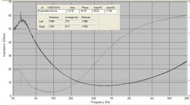
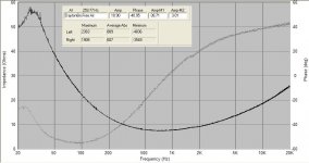
Free Air Impedance of a Dayton RS 8" Woofer, 8 Ohm
Phase axis is -60 to 60 degrees.
I copied the VU levels onto the chart.
Overall it looks close, but not prescise compared to the spec:
http://www.partsexpress.com/pe/showdetl.cfm?&Partnumber=295-366
The first attachment is a pdf with FR and Z charts.
Thanks for any help,
AC
Phase axis is -60 to 60 degrees.
I copied the VU levels onto the chart.
Overall it looks close, but not prescise compared to the spec:
http://www.partsexpress.com/pe/showdetl.cfm?&Partnumber=295-366
The first attachment is a pdf with FR and Z charts.
Thanks for any help,
AC
Attachments
Those Vumeter level are pretty low, which means more noise.
However, I don't understand how with a loop cable you get a 23.4k with MLS signal, which becames 869 on left during calibration.
A possibility is that the SC output can't handle the low impedance, therefore try with the SC headphone output, instead of the line out; just pay attention at the levels, or a fried Mobil pre will result.
Okay, set the levels and I still have the problem, only less so now.
22k for MLS, 18k for Sine 1k.
Measurements come in 5k for low impedance loads.
It is now identifying and measuring resistors correctly.
But the calibration file and driver impedance charts are VERY noisy. All over the place. I'd post charts, but I'm short on time right now.
So Claudio, that seems to be the problem. The MobilePre can't drive a low impedance load from the line in, but can a bit from the headphone jack, albeit noisy.
So it looks like I'm going to need an external amp for all my tests (or a better sound card )
I have a car amplifier and 12V power supply from a previous subwoofer. It's a MOSFET amp, so I'm not sure how good it is from an audiophile standpoint, but it HAS to be better than the noise coming off the headphone amp.
I'll work up a new jig to go through the amp tomorrow night and re-test.
Thanks again for the help. Looks like I'm on the right track. Just not there yet.
22k for MLS, 18k for Sine 1k.
Measurements come in 5k for low impedance loads.
It is now identifying and measuring resistors correctly.
But the calibration file and driver impedance charts are VERY noisy. All over the place. I'd post charts, but I'm short on time right now.
So Claudio, that seems to be the problem. The MobilePre can't drive a low impedance load from the line in, but can a bit from the headphone jack, albeit noisy.
So it looks like I'm going to need an external amp for all my tests (or a better sound card
) I have a car amplifier and 12V power supply from a previous subwoofer. It's a MOSFET amp, so I'm not sure how good it is from an audiophile standpoint, but it HAS to be better than the noise coming off the headphone amp.
I'll work up a new jig to go through the amp tomorrow night and re-test.
Thanks again for the help. Looks like I'm on the right track. Just not there yet.
That's why with only the sound card powering the DUT, you need to keep the volume levels low. I too found my graphs "got wild" towards the upper frequencies when I was just below clipping level when volumes set to the 25K mark. I found lowering the volumes to the 9K level helped. I'm using some cheap SoundBlaster PCI clone (don't know the model). It is only capable of 44.1KHz sampling.
In your case, if increasing the sound card volume helps to get more accurate resistor readings, then it must be a good thing.
My right channel volume levels are also considerably lower the left (reference).
I haven't yet used an external amplifier for impedance measurements, but will try it. I've avoided up until now to eliminate any risk of burning my soundcard with a direct cable connection.
Cheers,
DAvid.
I tried with low levels and it still gave me fits. Higher resistors measured well and lower ones were mis-identified. All the while, the signal levels were EXTREMELY low. I'm convinced Claudio is right and for whatever reason, the SC cannot handle a low load.
The next thing I am going to try is putting a 1k resistor in series with both the left and right signal by the output.
This is not a voltage divider, but more of a current limiter. That should allow the output terminal of the sound card to "see" around a 1k impedance regardless of the device under test.
I guess the real test then becomes whether or not the sound card is sensitive enough to measure the smaller voltages that will result. Since I have up to 60dB input gain pots on this particular model, I think I'll be fine, but the only way to know for sure will be testing.
And working in two resistors is a lot easier than re-rigging for an external amplifier setup, so I'll try it first.
More results to follow.
Still not working, but I think I know why. I put the 1k resistors in the wrong part of the circuit. I put them in the end of the circuit, by the line-in cables to the sound card. Since I was just trying to use one resistor per channel and not a true voltage divider, this essentially did nothing.
There was still the low impedance loop at the "front" or Line-Out side of the jig that was over-taxing the sound card and resulting in no output.
I need to move the 1k resistor there to show the SC output a much higher load, then I can get accurate readings off of the jig.
DOH! DOH! DOH!
If I'd drawn the circuit diagram first instead of just building it I would have caught the error. Instead, another 2 hours spent stripping wires and screwing things down to the terminal strip
Oh well, I'll get this eventually. Thanks again for all the help, guys. Your websites, writeups, and posts (both here and elsewhere in the forum on this topic) have been a great help!
A
arc2v--
I'm sorry you're having so much trouble getting this to work. As you've already discovered, the stereo line out can't drive much below 5 kOhm, and the mono line-outs can't go much below 1 kOhm. I found that out myself when I started using my MobilePre. Adding 1K resistors in series with the cable will give you higher VU readings, but not accurate results, as they will be acting as voltage dividers with whatever the true load is. I simply built a quickie battery-powered TDA2050 (you could use LM1875, too) that runs off 2x9V batteries. Since the minimum gain on the TDA2050 is like 26dB, I have an input stage with an opamp buffer with selectable attenuation, with one setting that reduces the incoming signal by 26dB so that the system behaves like a unity-gain buffer. Yeah, I know, it increases noise, but it seems to have worked so far. Other attenuation settings for other things.
Maybe a BUF634 would work...it's specified down to 50 Ohm load in the data sheet. But 1Vrms across 4Ohm is really pushing it's 250mA current output. Maybe an OPA541 or the like, they're unity-gain stable, but you'll need more than a couple 9V batts to drive them. +/-10V supplies minimum.
Regardless, you need some sort of external amp. You won't get high-quality results without one.
Hope this helps--
Greg
Thanks Greg.
I just wanted to try everything before resorting to the external amp. Luckily, I have one, so it won't be that big of a deal, but I wanted to keep things simple if possible.
I'm guessing people who have gotten good results without one must have an amplified sound card.
Question about why the voltage divider lowers accuracy: is it because the new readings are at much lower voltage? The card then becomes less sensitive? I was hoping the MobilePre's preamp stage could compensate for the divided input voltage.
Regardless, I'm pretty sure I can make this work with the parts I have now -- it's just a matter of putting them together in the right order.
Once again: I may even end up building a speaker sometime
Some details on the amp I plan on using (in case you all think it will be awful).
It's a California Audio car amp powered by a radio shack regulated 12V power supply. I used this setup to power my subwoofers for a long time until I got an NHT SA-2 (I wanted more crossover control).
It's a MOSFET amp, but it's stable down to 2 Ohms. I believe it was 65W per channel RMS. I have no idea what the input and output impedances, or the noise spectrum is like. It has that compressed high feedback sound (which was fine for while, subwoofers only), but I imagine it will have decent noise performance from all that feedback.
I'll have to measure P-P voltage to figure out for sure, but I imagine it would be 16V or so (P=V^2/R, P=65W rms into a 4 Ohm load, V=sqrt(P*R)=16.1). Oversimplified, I know. It has a gain control, so I may be able to limit the output voltage using that, but at what cost to the SNR or distortion?
Please let me know what some of the other pitfalls might be. I'll try to take some measurements tonight or tomorrow.
The amp does have a gain control knob that I used to set the subwoofer level. The real question is whether or not the output impedance of the MobilePre and the input impedance of the amplifier will mesh well.
I have a request in to M-Audio to get the output impedance for the 2 mono or one stereo output. Since it is designed to act as a microphone or instrument preamp (and recording interface), I'm reasonably sure it can drive an amplifier directly from its outputs.
I'm relearning a lot about electronics I forgot a long time ago (like Node-Voltage and Mesh Current methods, impedance matching, etc) and stuff I never knew (like op-amp design or MLS waveforms).
- Status
- This old topic is closed. If you want to reopen this topic, contact a moderator using the "Report Post" button.
- Home
- Loudspeakers
- Multi-Way
- Speaker Workshop Distortion Question