I made a mistake earlier when I said 12-24VAC, it should be 12 to 16VAC, 1 amp.
 ... that stings a little
I spent the better part of my shift yesterday milling a spot for a 120v to 20v transformer into the enclosure I'm fabbing together.

revision 3 here I come ...lol
I spent the better part of my shift yesterday milling a spot for a 120v to 20v transformer into the enclosure I'm fabbing together.
revision 3 here I come ...lol
Sorry Jarrett,
My original had a 35V cap in that position. I changed it to 25V for economy in the kits.
20VAC would exceed the rating on the smoothing cap.
no biggy... I'm just going to add a voltage divider to dail in the appropriate value.
edit: Actually, I do have some 35v caps at my disposal. Anything else besides the smoothing cap I should be concerned about, if I run it at the 20vac?
edit2: Never mind... I just checked the PCB and saw they'll all rated for 25v. Voltage divider it is...!
edit: Actually, I do have some 35v caps at my disposal. Anything else besides the smoothing cap I should be concerned about, if I run it at the 20vac?
edit2: Never mind... I just checked the PCB and saw they'll all rated for 25v. Voltage divider it is...!
Last edited:
no biggy... I'm just going to add a voltage divider to dail in the appropriate value.
edit: Actually, I do have some 35v caps at my disposal. Anything else besides the smoothing cap I should be concerned about, if I run it at the 20vac?
edit2: Never mind... I just checked the PCB and saw they'll all rated for 25v. Voltage divider it is...!
If you are staying with the 20VAC transformer, it is best if you change the smoothing cap (C7) and the decoupling cap (C3) to 35V. Nothing else will need to be changed.
Me again....
By chance do you have any 35v 4.7mF caps laying around john...?
Best I've got is 63v, and needless to say, it has some girth to it. Not to mention another 3/4" of length...lol.
I do have a shorter 6.8mF at 50v, but it has the same circumference as the 63v beast. I'm not sure the effect playing with the capacitance will have on the circuit. So I thought it best to continue assembly with a 35v C7 in mind.
I'm off tomorrow so the hunt will be on. Any electronic supply shops in the area you can think of?
I can picture it finished...
John
I am planning to start assembling my jig this weekend and need some help with finishing the enclosure (great simple design by the way).
What would you suggest to somebody that is not known for his painting skills?
Since I do not have a spray gun, I need to stick with "products in a can" if you get my drift.
I am not looking for anything fancy, but want to have a nice bright color just like yours.
I thank you in advance for any advice you can provide.
Hi Duda,
I used 2 products in finishing mine and both are in spray cans. First, I sanded the box really smooth - be careful when sanding not to damage the slot that holds the front and back panel.
Next I sprayed on a coat of clear polyurethane on the box, inside as well. This is the sealer coat. I let that dry overnight then sanded that smooth with fine paper the next day. Another coat (or more) of clear polyurethane as the primer coat and let that dry a few hours. Lightly sand with fine paper and you are ready for finish coats. I used Tremclad rust paint and gave it several coats, just letting it dry between coats for an hour.
Patience is key and getting the primer coat smooth means the finish will be smooth.
This can give a pretty good paint job for less than $20.
Hope that helps
Jumpers
John,
Just finished building my Jig, great quality. You might want to include the jumpers in your instructions, get a sense that some of those who build this may be newbies and miss the need for them. I read your assembly instructions and did not find a refernce to them.
Mike
John,
Just finished building my Jig, great quality. You might want to include the jumpers in your instructions, get a sense that some of those who build this may be newbies and miss the need for them. I read your assembly instructions and did not find a refernce to them.
Mike
Hi Mike,
Yes, I thought of that after and I've been meaning to get a mod to insert a post in there covering it but I've just been too busy.
The new boards have "jumper" printed on in the silkscreen:

It's hard to think of everything - we have a "work in progress" here.
Glad you like the jig - have you tried it yet?
Yes, I thought of that after and I've been meaning to get a mod to insert a post in there covering it but I've just been too busy.
The new boards have "jumper" printed on in the silkscreen:
It's hard to think of everything - we have a "work in progress" here.
Glad you like the jig - have you tried it yet?
Hi Duda,
I used 2 products in finishing mine and both are in spray cans.
...
This can give a pretty good paint job for less than $20.
Hope that helps
Thanks John - I think I can managed that...
For the wall wart I have on hand a Hon-Kwang Class 2 transformer: It came from some Christmas light LED string thingy...which never worked right and pissed my mom off a few years back. It would light up and then shut off quickly. One of those multi-color, multi program thingies.Input: 120V 60Hz 18W
Output:12VAC 840mA
so...840mA= .840A.
Suitability: at least for testing or temporary use 'til I find a bigger one?
A]: "...more power, Scotty!"
B]: "...she can't take much more of this, Captain!"
C]: "...Beam me up Scotty...there's no intelligent life here!"
Hi,
well done MJL.
Everything fits.
I am glad I did not have to source all the hardware to fit those footprints.
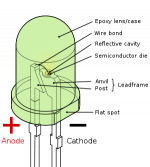
Can someone confirm the orientation of the ON LED? I think the LED flat goes to SW2 side and the longer leg faces towards the outside of the PCB.
Thanks for all your efforts.
well done MJL.
Everything fits.
I am glad I did not have to source all the hardware to fit those footprints.
Can someone confirm the orientation of the ON LED? I think the LED flat goes to SW2 side and the longer leg faces towards the outside of the PCB.
Thanks for all your efforts.
I put the LED flat side [cathode, short lead, or negative] facing to the inner portion of the panel and the other lead [anode, long lead, positive] to the outside of the front panel. I could well be very wrong on this.
I do recall being confused because of trace route FROM LED through R1, through jumper and over to negative side of 4700uf capacitor.
The other trace route comes direct from diodes.
The confusing part is I'm more familiar with the resistor in series on the power supply side, and now it's been awhile since I assembled it so it's not that fresh on the brain.
I haven't run any power through it yet, though...
I think I based my logic for install on this diagram:
Attachments
Last edited:
I think my wall wart has the wrong diameter inner hole for the out plug. i suspect 2.5mm or greater, though the outside barrel is correct.
So...I'll change plug barrel or just get the 1 amp unit.
Now I recall the wall wart came from a small Christmas tree on a rotating stand with a single bright bulb at its base and fiber optic lines above the glass [mulit-color] lens the fiber optic lines change color as the tree spins.
I have been thinking of adapting parts for a psychedelic volume control bezel for a preamp, with small dots of light around the bezel changing color as the volume increases to full volume showing the atomic symbol, all lit up nice and bright with extra strands of light pipes. Johhn's face-plate etching would be a perfect methodology for this custom bezel circumferencing the volume knob.
I digress...as usual.
Last edited:
I don't know what sise my plug is but it seems sloppy a bit when fitting over the male inner prong on the board input until the outer barrel centers it well.
That inner male prong on the circuit board looks smaller than my transformer plug orifice, but 4/10 of a mm is hard to judge.
That inner male prong on the circuit board looks smaller than my transformer plug orifice, but 4/10 of a mm is hard to judge.
- Status
- This old topic is closed. If you want to reopen this topic, contact a moderator using the "Report Post" button.
- Home
- Design & Build
- Construction Tips
- Speaker Testing Jig Assembly Thread