Hello please help struggling to find any information on net. Basically when I move my pot the speaker cone goes in and out quite far. It has small crackle but its not the pot I have change to 3 different pots and they all do the same:
Original pot alps 50k x2
changed to cheap 50k x2
changed to another decent 50x2 pot
On all of them the speaker cone moves quite far in and out but the sound is perfect! It just moves the cone a lot. Is the amp faulty? its an old Aura integrated amp. Any idea what can cause this? I have already tried servisol 10 on all 3 of the pots!! Cheers
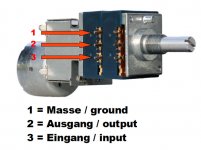
One of the end pins should be ground, the other end pin is the input, and the middle pin is the output. Turn the volume all the way down. Now measure DC volts from end pin to end pin. Check both sections of the pot. Don't play music. Are both channels doing the same thing? 7.8VDC is not good and that's the problem, now where to go from here. What is it that you are working on?
Craig
Craig
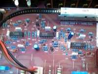
I think there is more than one manufacturer using the Aura brand globally. Being in the UK I assume you mean B&W Aura from around 20 years ago but there were several models including VA50, 80, 100 and revisions. How about identifying the manufacturer and model?
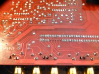
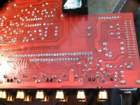
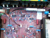
Most commonly, there will be a capacitor - an electrolytic type in series with both the input and output connections of the pot. which can be seen and traced from the copper pattern underneath. The purpose is to block DC from flowing through the pot but permit signal to pass unimpeded. However, electrolytic caps and similar large value capacitors do fail in time. Replace with like for like and note they are probably polarized - observe any stripe on the sleeve label that indicates the negative terminal and match that to the marking on the PCB or to how that marking on the original part was aligned. Look carefully for polarity indication before removing caps.
Most commonly, there will be a capacitor - an electrolytic type in series with both the input and output connections of the pot. which can be seen and traced from the copper pattern underneath. The purpose is to block DC from flowing through the pot but permit signal to pass unimpeded. However, electrolytic caps and similar large value capacitors do fail in time. Replace with like for like and note they are probably polarized - observe any stripe on the sleeve label that indicates the negative terminal and match that to the marking on the PCB or to how that marking on the original part was aligned. Look carefully for polarity indication before removing caps.
I need some help please. I replaced the 3 caps on the top of the board and it made no difference still getting 7.8 v on ground and inputs pins.
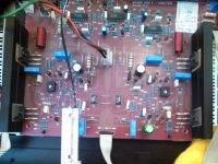
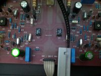
I know that is comes from the thick grey cable from top of board but I cannot for the life of me figure out how the sector switch is feeding the circuit the sound!!?! looking at the bottom of the board it just does not go anywhere but the thick grey cable and the RCA inputs. Am I really that stupid?
if there is no input the volume does not crackle but if there is an input even with with the source muted it has the dc problem. I think its the input switch but I know I'm dead wrong!
Attachments
-
 WP_20170121_007.jpg451.5 KB · Views: 56
 -
 WP_20170121_006.jpg513.4 KB · Views: 72
 -
 WP_20170121_005.jpg453.5 KB · Views: 66
 -
 WP_20170121_004.jpg475.4 KB · Views: 70
 -
 WP_20170121_003.jpg421.7 KB · Views: 150
 -
 WP_20170121_002.jpg588.5 KB · Views: 148
 -
 WP_20170121_001.jpg626.5 KB · Views: 164
 -
 WP_20170120_002.jpg460.8 KB · Views: 163
Hi Jaycee, they look like they were always in there and not custom fitted. It gets barely warm after 2-3 minutes I did check voltage pins 4-7 and it has 13.6 and 13.9 on both, I think one was a negative but I swapped my leads around after checking the first opamp. Thanks
I did another test the headphone out also has the same crackling
I did another test the headphone out also has the same crackling
OK those voltages sound correct. I think i'd need to find a schematic to comment further.
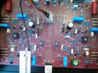
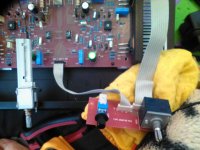
What I would do next is I would disconnect the grey cable at J11, and test between L - GND, and R - GND on the cable. If the DC is there, then the fault is in the preamp part of the circuit. If it is not there, and you are seeing DC at the speaker terminals, then you have a power amp fault.
If it's the preamp, and you want to try a "shotgun" fix, replace those two TL084 opamps. From the board layouts, it doesnt appear that there is any input protection, and it's possible an ESD event has killed one of the opamps partially.
EDIT: Do *NOT* connect your speakers while the amp has this problem. DC will kill the voice coils in the speakers. If you want to see if the problem is still there or not, measure the DC voltage at the speaker outputs. With no signal, there should be no more than a few hundred millivolts at best.
thanks for your help. Its 100% in pre-amp as I mentioned in earlier post the thick or better word wide grey cable thats where the dc is coming from. But I cannot find any caps up there as suggested earlier by Ian.
I just cannot understand where the sound goes after the input selector. I have tried following the sound via meter on beep but cannot find for the life of me how the input selector connects with the rest of the circuit. Also I did find circuit diagram but the numbers are wrong so its little different
I just cannot understand where the sound goes after the input selector. I have tried following the sound via meter on beep but cannot find for the life of me how the input selector connects with the rest of the circuit. Also I did find circuit diagram but the numbers are wrong so its little different
Attachments
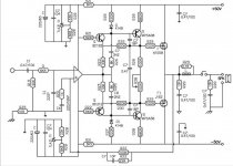
The circuit shown there is for one channel of the power amplifier section. That explains what IC5 and IC6 are for - they are the opamps (one for each channel) shown in this schematic.
Working blind here.. so...
Measure the voltage to ground on each pin of IC2, ie, use your red probe on each pin of the IC, and connect the black probe to a ground point. Pin 1 is marked with a circle, and pin numbers go anticlockwise around the chip. Pin 4 should be +13v and pin 11 should be -13v. Report those numbers back here.
- Status
- This old topic is closed. If you want to reopen this topic, contact a moderator using the "Report Post" button.
- Home
- Amplifiers
- Solid State
- Speaker cone moving not faulty pot