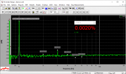
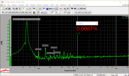
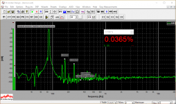
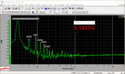
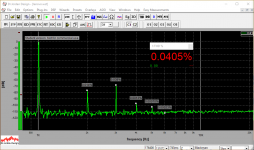
15m cable, dummy load, measuring at far end (the load)
OK... got some material
First - raw spectrums for different measurement configurations.
In the end - summary table.
Starting with dummy load as a reference.
OK... got some material
First - raw spectrums for different measurement configurations.
In the end - summary table.
Starting with dummy load as a reference.
Attachments

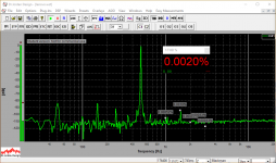

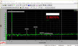
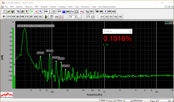
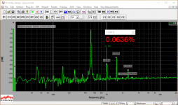
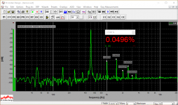
3m cable, speaker, measuring at the amp terminals
From now on - it will be a speaker, rated as 6 ohm.
Starting with the relatively short 3m cable.
From now on - it will be a speaker, rated as 6 ohm.
Starting with the relatively short 3m cable.
Attachments
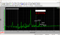


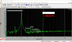
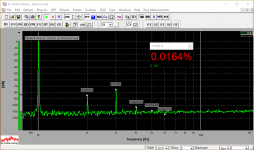
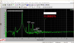
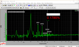
3m cable, speaker, measuring at the far end (speaker)
Now - same 3m cable, but measuring right at the speaker.
All measurements are done at 30, 50, 85, 100, 200, 500 and 1000 Hz.
Now - same 3m cable, but measuring right at the speaker.
All measurements are done at 30, 50, 85, 100, 200, 500 and 1000 Hz.
Attachments


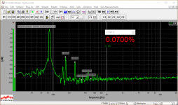

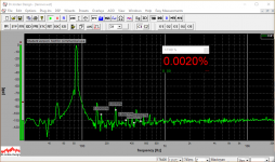
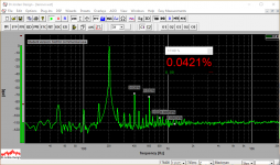
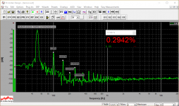
15m cable, speaker, measuring at the amp terminals
OK, now - the long cable, measuring close to the amplifier.
OK, now - the long cable, measuring close to the amplifier.
Attachments


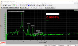


15m cable, speaker, measuring at the far end (speaker)
Finally - the same long cable, measuring right at the speaker.
Finally - the same long cable, measuring right at the speaker.
Attachments


SUMMARY
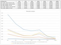
Here are the table and the diagram.
All measurements are done at 4V RMS at the output of the amplifier.
I could not go higher as it was rather loud already with the speaker - I couldn't hear normally for about an hour At 200Hz the lights at the ceiling were vibrating, adding some "ringing" to the sound from the speaker.
Pretty interesting. Distortion peak at 200Hz is clearly visible - that's where the speaker's impedance is at the minimum.
With the long cable, low-frequency signals experience noticeable distortion increase.
However, with a 3m cable, performance at the speaker end is pretty good.
Cheers,
Valery
Edit: added a pdf with much better resolution
Here are the table and the diagram.
All measurements are done at 4V RMS at the output of the amplifier.
I could not go higher as it was rather loud already with the speaker - I couldn't hear normally for about an hour
At 200Hz the lights at the ceiling were vibrating, adding some "ringing" to the sound from the speaker.Pretty interesting. Distortion peak at 200Hz is clearly visible - that's where the speaker's impedance is at the minimum.
With the long cable, low-frequency signals experience noticeable distortion increase.
However, with a 3m cable, performance at the speaker end is pretty good.
Cheers,
Valery
Edit: added a pdf with much better resolution
Attachments
Last edited:
Now you know the truth. Feedback need to be taken straight from load terminals or non-feedback amp must be placed straight at load. Output LR-filter must be compensated at all audioband. Wire resistance must be compensated at least to 1 kHz. Passive filters must be avoided. So best system is an active-DSP system with per-channel amplifying.Finally - the same long cable, measuring right at the speaker.
Yes. Load there are mostly current-consuming and damping factor (for a feedback'ed amp) mostly determined by cable resistanse. So voltage drop on the wire resistance is at maximum and you see distortion at load side.Distortion peak at 200Hz is clearly visible - that's where the speaker's impedance is at the minimum.
Last edited:
Cable resistance does not generate distortion; metallic conductors are highly linear. However, high cable resistance (i.e. a poor cable, either too long or too thin) can expose other problems such as damping or speaker nonlinearity.xrk971 said:For one thing, you can’t test *all* cables, and certainly high impedance thin gauge cables can’t be the same as low impedance thick conductor cables. If an amp is sensitive to load impedance it will have an effect. If a speaker is sensitive to an amp’s output impedance, it will have an effect and sound different. I know that the DF of an amp really changes with cable and without a cable attached to the dummy load.
Minimum speaker impedance means maximum effect of speaker nonlinearity making distortion current visible. The distortion current is still there with no cable but you can't see it so easily. You are actually measuring an aspect of speaker nonlinearity, not cable nonlinearity. This may disappoint some people.vzaichenko said:Pretty interesting. Distortion peak at 200Hz is clearly visible - that's where the speaker's impedance is at the minimum.
<——of non highly damped speaker——>You are actually measuring an aspect of speaker nonlinearity, not cable nonlinearity.
Cable resistance does not generate distortion; metallic conductors are highly linear. However, high cable resistance (i.e. a poor cable, either too long or too thin) can expose other problems such as damping or speaker nonlinearity.
Minimum speaker impedance means maximum effect of speaker nonlinearity making distortion current visible. The distortion current is still there with no cable but you can't see it so easily. You are actually measuring an aspect of speaker nonlinearity, not cable nonlinearity. This may disappoint some people.
Exactly - the cable is no problem. The "bad thing" is the speaker - a rather non-linear system. Especially at the low frequencies. The longer the cable - the higher output impedance is seen by the speaker - the less non-linear speaker is controlled by the amplifier's output.
The "closer" the speaker to the amplifier - the lower the distortion is. We can make it closer either with a shorter cable, or with a"fatter" cable. These properties are not equal, but still - it makes sense to use the shorter and the fatter cables for better control of the speakers = lower distortion. Assuming the amplifier provides the output impedance low enough and the output current high enough when required.
Damping and nonlinearity are two quite separate issues. Don't confuse them.BesPav said:<——of non highly damped speaker——>
There are people who advocate going to the opposite extreme: current driving of speakers. Their logic is that it is current which moves the voice coil, so if the current is set by the amplifier (instead of the voltage) then the result will be more transducer linearity. If they are right then you can get some of the advantage of this method by using long thin speaker cables from a conventional voltage-source amplifier.vzaichenko said:The "closer" the speaker to the amplifier - the lower the distortion is. We can make it closer either with a shorter cable, or with a"fatter" cable. These properties are not equal, but still - it makes sense to use the shorter and the fatter cables for better control of the speakers = lower distortion. Assuming the amplifier provides the output impedance low enough and the output current high enough when required.
I am not convinced that they are right. Speaker nonlinearity has various causes but there is no a priori reason to assume that current drive is better. For one cause of nonlinearity (voice coil displacement in a non-uniform magnetic field) I think voltage drive is better: as the voice coil moves out of the gap it will generate less force but also less back emf so with a conventional system the current will increase to partly compensate; a current-driven system cannot compensate. Suspension nonlinearity could act in the same way: if anything tends to restrict the motion this will increase the current in a conventional system, but not a current-driven system.
That is one of the beauties of audio: whatever the physics says, there are always people who take the opposite view.
Try to understand and differentiate the causes and consequences. This nonlinearity was caused by voltage drop on wire resistanse, which created by flowing current. Measurement setup indicates this as distortion.Damping and nonlinearity are two quite separate issues. Don't confuse them.
If Valery could take measurements while speaker will be connected straight to amplifier output terminal (and amp’s feedback is taken from output terminals, not somewhere from the amp’s PCB) - there will be much less nonlinearity.
...
That is one of the beauties of audio: whatever the physics says, there are always people who take the opposite view.
I'd call that a wart
//
That is what I am trying to get you to do.BesPav said:Try to understand and differentiate the causes and consequences.
No. The nonlinearity is in the current. The cable resistance merely makes this visible; it does not cause it.This nonlinearity was caused by voltage drop on wire resistanse, which created by flowing current. Measurement setup indicates this as distortion.
No. The nonlinearity would still be there, but we would no longer be able to see it. The nonlinearity is caused by the speaker impedance being nonlinear. The cable is linear.If Valery could take measurements while speaker will be connected straight to amplifier output terminal (and amp’s feedback is taken from output terminals, not somewhere from the amp’s PCB) - there will be much less nonlinearity.
No. The nonlinearity are caused by wire resistance.No. The nonlinearity is in the current. The cable resistance merely makes this visible; it does not cause it.
Nonlinearity of speaker impedance doesn’t cause signal distortion. It can cause phase lag, it can cause huge current, but not distortion.No. The nonlinearity would still be there
It will be damped/shunted by low amp’s output resistance connected in parallel. There will be some milliOhms and lower depending of amp’s feedback depth at a given frequency.The nonlinearity is caused by the speaker impedance being nonlinear.
Distortion was caused by bad damping. Bad damping caused by improper feedback point and small but finite connection resistanse.

Last edited:
You are saying that wire resistance is non linear??No. The nonlinearity are caused by wire resistance.
LMAOYou are saying that wire resistance is non linear??
Of course - no.
[emoji6]
(UPD
But really, your wire is a strongly capacitive for my amp based on MRF6S18060N)
It replaces relatively low amp’s output resistance and interacts with nonlinear load. Low load impedance at some frequency causes higher current to run through the load. That current causes voltage drop in all loop elements. Our measurement setup sees part of voltage drop, being caused by that current at wire resistance (or being divided at load voltage) as distortion.
Voila.
Last edited:
- Status
- This old topic is closed. If you want to reopen this topic, contact a moderator using the "Report Post" button.
- Home
- Amplifiers
- Solid State
- Speaker cables don't influence harmonic distortion!