Simon, I did a quick and dirty calculation again. Assume a 15 foot run (30 ft here-and-back). The skin effect from a #12 solid conductor will drop the response by about 0.15dB at 20kHz. Using an extension cord like I have, with coarse strands, the drop is quite a bit lower, more like 0.05dB.
This will not keep me up at night worrying.
As already mentioned not a major issue but a measurable one. If your tweeter is a high efficiency unit (not common in HiFi very common in Pro) there can be a back EMF of 10% or more. To control this via the audio power amplifier's feedback requires adequate bandwidth. So 200khz is not completely unreasonable to try to achieve in your loudspeaker cable. When you allow for damping factor, etc, it is a small issue, but a real one.
So there actually can be differences that a good ear can hear between solid and stranded wire. Oxides increasing the resistance on the outer surface will also play a a part of the mechanism. There really is a dependence on the amplifier design and the loudspeaker for cable sensitivity.
You really should place this worry on your list right after monsters under your bed. (For those who live in tropical areas where there actually may be big green things under your bed, move it even farther down the list.)
for most cables Proximity Effect is larger than Skin Effect
isolated cylinders aren't too useful as audio cables, the proximity of the return current conductor greatly modifies the current distribution
isolated cylinders aren't too useful as audio cables, the proximity of the return current conductor greatly modifies the current distribution
quickfield seems to be fairly complete for 2-d eddy current simulation, "time-harmonic" and "transient magnetics" simulations can vary conductivity and permeability, transient can model nonlinear permeability but both ignore permitivity-displacement current so it isn't a full E-M simulation
the student version is the first free E/M simulation package i've gotten to do anything remotely plausible without crashes and seizures, i was also able to create my own models and run them with only a few hours of playing with the user interface
cool pictures and most numbers you might want are readily available, time series plotting doesn't appear to include integral results, particularly total current over the cross section of the conductor that would be handy for device terminal characterization in transient mode
their "active field" interface does look like a solution to getting device terminal currents from the transient analysis, examples are given to define problems, control simulations, export and plot with visual basic/word macros - the bored or motivated could probably program a cable simulation to give the current from a sine burst in a transient analysis in a few days, and then explore the effect of magnetic vs non magnetic conductors in minutes
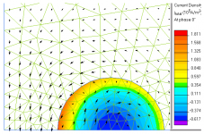
...I’ve learned more about how to control meshing (shown) and exploit symmetry, same 2mm cu wire 4mm cntr, 20 KHz current at phase = 0 from harmonic analysis and B field vector plot:
Attachments
Last edited:
A few entertaining links:
http://www.audioholics.com/education/cables/cable-distortion-and-dielectric-biasing-debunked
http://www.audioholics.com/education/cables/calculating-cable-inductance-of-zip-cord
http://www.audioholics.com/education/cables/cross-coax-cables-design-vs-zip-cord
http://www.audioholics.com/education/cables/debunking-the-myth-of-speaker-cable-resonance
http://www.audioholics.com/education/cables/skin-effect-relevance-in-speaker-cables
http://www.audioholics.com/education/cables/interview-with-dr-howard-johnson-about-skin-effect
http://www.audioholics.com/education/cables/silversmith-audio-cables-interview
Last edited:
Yes it's affected by the location of the return path or proximity to ground planes or other modifying factors, but that doesn't change the fact that it also varies with diameter.The external inductance of a wire is completely dependent on the location of the return current path.
Of course these other factors affect it too, and a stripline is not exactly the same as a round conductor but the fact remains that if you change the width you are changing the cross sectional area and the inductance does indeed change.A stripline inductance depends on the aspect ratio of the conductor, the distance to the groundplane if it's referenced to it, or to the return conductor, and the permittivity of the substrate, be it g-10, alumina (Al2O3), or beryllia..the two latter being ceramic substrates that I did indeed work striplines on.
John,Now, I will repeat exactly what I just told you..pay attention this time..
Now, go back to the web pages you cited, and examine the equations very closely. Note that all the equations have a frequency term in them. These equations are calculating exactly what skin effect/proximity is doing to the internal inductance as a result of current redistribution caused by skinning. Note that when the current is fully skinning at the surface, there is no internal inductance. See also the note on the right..these equations are exact only at DC and infinity..care to guess why?
In your haste to prove me wrong, did you even look at the equations for more than 5 seconds ? The first one on K7MEM's page has no frequency term in it at all. The terms in the equation are wire radius and wire length, along with a 0.75 constant which approximates skin effect at "low" frequencies where skin effect is small. Wire diameter and length are the only factors affecting inductance of a single solid wire in free space at "low" frequencies.
Now look more closely at the forumlas referenced on wikipedia, which you claim have a frequency term in them. There are actually three sets of formulas shown for straight wire conductors - the first more complex one only applies to a conductor with magnetic permeability and does not apply to a copper wire. (You'll notice that a cylinder radius term is still present though even in this case)
Of the two remaining formulas which are applicable for copper/aluminium there is no frequency term in the equations, but there is a diameter term. f is mentioned to the right hand side but only in relation to estimating skin effect based on frequency and wire area to guide you which constant to use, ( 1 or 0.75) where 0.75 is no skin effect. The equation on the first site is exactly the same as this 3rd equation, using 0.75 as the constant.
Although you could say there is a frequency component incorporated in the 0.75 constant, (albeit one that varies depending on wire construction, not just frequency) the maximum change between no skin effect and maximum skin effect is relatively small as I mentioned last time, with most of the skin effect change being resistance. Despite your claims that diameter is not relevant, diameter is a major term in the equation, independent of any frequency dependant changes in skin effect that might be incorporated in the 0.75 / 1 constant.
Therefore your claim that wire diameter does not affect inductance at low frequencies is wrong, unless you care to dispute the validity of the equations.
Last edited:
I have done so. A cylindrical conductor has 15 nH per foot internal inductance at DC. The external inductance of a wire is completely dependent on the location of the return current path.
If you wish, I can cite textbook references...Jackson, Becker, Rojansky, Shadowitz...
A stripline inductance depends on the aspect ratio of the conductor, the distance to the groundplane if it's referenced to it, or to the return conductor, and the permittivity of the substrate, be it g-10, alumina (Al2O3), or beryllia..the two latter being ceramic substrates that I did indeed work striplines on.
If you are going to use the net to provide factoids, please research the topic a tad more...you are speaking about a stripline, not a cylindrical conductor.
The inductance per foot is independent of wire diameter.
Now, I will repeat exactly what I just told you..pay attention this time..
Now, go back to the web pages you cited, and examine the equations very closely. Note that all the equations have a frequency term in them. These equations are calculating exactly what skin effect/proximity is doing to the internal inductance as a result of current redistribution caused by skinning. Note that when the current is fully skinning at the surface, there is no internal inductance. See also the note on the right..these equations are exact only at DC and infinity..care to guess why?
Cheers, John
"A cylindrical conductor has 15 nH per foot internal inductance at DC."
This statement makes no sense to me at all, perhaps you could explain it. Inductance is customarily thought of as a parameter that is independent of frequency. However who am I to argue the point. But it does seem strange that you would pick DC. After all, the reactive impedance of an inductor is X(L)=j2pi*f*L therefore at DC the inductive reactance is zero. So what is the significance of inductive impedance at DC?
Hi,
I may be mistaken, but I believe this number shows where the skin effect reaches a certain level (IIRC it is where only 70% of the wire is effective) , it obviously starts at a much lower frequency, but is of a lesser magnitude there...
Past that we are back at the point where due to any numbers of factors cables acquire more complexity and more issues than the simplistic "everything must sound the same or it is defective" world-view allows for and can stomach.
Ciao T
18 Gauge wire skin effect starts in theory at 17khz. (American Wire Gauge table and AWG Electrical Current Load Limits with skin depth frequencies)
I may be mistaken, but I believe this number shows where the skin effect reaches a certain level (IIRC it is where only 70% of the wire is effective) , it obviously starts at a much lower frequency, but is of a lesser magnitude there...
Past that we are back at the point where due to any numbers of factors cables acquire more complexity and more issues than the simplistic "everything must sound the same or it is defective" world-view allows for and can stomach.
Ciao T
Last edited:
isolated cylinders aren't too useful as audio cables, the proximity of the return current conductor greatly modifies the current distribution
Ah..a point here..at that time, my moniker was sully. I changed it to be consistent forum to forum.
The equations you've linked to have embedded wire size and frequency together. As I said before, the internal inductance of a wire will be modified by the skin effect, varying from 15 nH per foot at DC, to zero at infinity. That is why the note on the right hand margin specifically states that the equations are exact only at DC and infinity, all other cases are approximations.Yes it's affected by the location of the return path or proximity to ground planes or other modifying factors, but that doesn't change the fact that it also varies with diameter.
Actually, it is not as trivial as you would expect. When the aspect ratio is changed, (width vs thickness), the resultant reluctance path around the conductor becomes longer. This results in lower inductances for flatter conductors. So cases of rectangular cross section are a bit more complex than that of a cylinder.Of course these other factors affect it too, and a stripline is not exactly the same as a round conductor but the fact remains that if you change the width you are changing the cross sectional area and the inductance does indeed change.
This is not what happens with pure cylinders.
In your haste to prove me wrong, did you even look at the equations for more than 5 seconds ? The first one on K7MEM's page has no frequency term in it at all. The terms in the equation are wire radius and wire length, along with a 0.75 constant which approximates skin effect at "low" frequencies where skin effect is small. Wire diameter and length are the only factors affecting inductance of a single solid wire in free space at "low" frequencies.
Of course I looked at it. For example, a #14awg 12 inches long has an inductance of .3 uH?? That is absolutely incorrect, it's a nonsense value incorrectly derived. You have assumed that the equation models reality.
I repeat the argument so you are clear...
YOU posted:""Skin effect at audio frequencies is a myth.""
I responded with a graphical presentation depicting both the exponential and bessel derivations of current density within a reasonable sized conductor.
Now look more closely at the forumlas referenced on wikipedia, which you claim have a frequency term in them.
I did. Perhaps you should.
First of all, the first equation does indeed work for both copper and aluminum. All you have to do is put the relative permeability of either material in.
Second, review the second and third equation. Note at the end of both equations is the thingy "" +0-3% ""..
THAT is how they are expressing skinning here. The zero represents the equation at DC. The minus 3% represents the loss of internal inductance as a result of skinning.
The maximum change is exactly 15 nH per foot, and it is that +0-3% term in the last two equations. That is the internal inductance of a cylinder of conductor with DC current flowing.Although you could say there is a frequency component incorporated in the 0.75 constant, (albeit one that varies depending on wire construction, not just frequency) the maximum change between no skin effect and maximum skin effect is relatively small as I mentioned last time
Therefore your claim that wire diameter does not affect inductance at low frequencies is wrong, unless you care to dispute the validity of the equations.
It is very important when viewing various websites to view with a cautious eye, whether the content is accurate or not.
One very important tool at your disposal is knowledge. Some very important tools:
1. The internal inductance of a cylindrical conductor is 15 nH per foot at DC, and goes down as frequency rises. Note: This is Mu zero/8 pi.
2. It is impossible to assign an inductance number to the external inductance of a single wire without consideration of the current return path. It is fictional, and it is actually infinite. Any site which claims a value of inductance of a wire by itself without the return path, other than 15nH per foot times the conductor relative permeability, is wrong. The external inductance cannot be calculated.
3. Any calculation of inductance vs size and frequency can use similitude. If both are increased consistently, the results remain the same. This is extremely evident if one uses the Terman equation to calculate the inductance of a twin pair, and then scales the geometry to another size, including the scaling of the insulation thickness. When a larger guage wire is chosen with the insulation thickness remaining constant, the inductance will lower. This is the origion of the thicker is lower inductance myth...the insulation thickness ratio to conductor diameter was ignored.
Edit: try the second or third equation on the wiki page with l = 300mm, d = 1 mm. I did it quickly, and got 425 uH per foot??? Either I messed up in haste, or that equation is quite incorrect.
Cheers, John
Last edited:
Unless someone can come up with a novel theory of non-linear distortion caused by wire, the only effect I'm aware of is the equivalent LCR parameters of the wire and how that fits into the network consisting of the source impedance (usually low) and the load impedance (usually high.) The cheapest wires have LCR parameters that have a negligable effect at audio frequencies in these networks. You have to go to extreme lengths to construct wire that is so bizarre to have an effect. Leave it to audiophiles to screw up anything, even a wet dream.
Hi,
This says nothing however about (for example) voltage developed across the ground conductors non zero resistance and inductance when different potentials between equipments grounds (caused by leakage from the mains, RF interception in the system and others), which can be quite material in terms of magnitude and are quite common.
In our cases such noises now appear in series with the signal, will be amplified etc. and appear quite measurable and often audible, especially when using the really cheap interconnect cables which have very little copper in them.
This is the problem with these isolated, first order views of things that are being advocated by some, such an approach makes sure that many material and real, observable phenomena are missed. Surprisingly one does not even need a new theory or anything. Really basic EE knowledge is perfectly sufficient.
For those who need a quick representation as to why interconnects and mains cables can make sonic differences that need no more than EE101 explanations, look at the following diagrams.
Those wishing to remain wilfully blind, do not look.
First, here a picture that represents what is being proposed as being the only thing that matters.
Such a simple, pretty and easy to understand picture, truly reminiscent of the Map of the Bellman in Lewis Carrol's "Hunting of the Snark"...
Now while those with blank maps happily tingle their bells, here a picture of what the REAL map looks like, two different cases shown...
Note, the above case shows only TWO interconnected devices. Many modern systems are by far more complex than that even before we add AV and Cable TV to the mix.
Drawing out the equivalent loops for the individual system is left to the individual readres, including those who think they can teach classes on grounding.
Ciao T
PS, the figures are from a review/article by Pete, who used to be quite active on RAHE and over at AA.
I wonder whatever happened to him. Probably had it up to here and some with smarty-pants know-it-all's telling him what was possible and what not, while showing an appalling lack of basic EE knowledge...
Unless someone can come up with a novel theory of non-linear distortion caused by wire, the only effect I'm aware of is the equivalent LCR parameters of the wire and how that fits into the network consisting of the source impedance (usually low) and the load impedance (usually high.) The cheapest wires have LCR parameters that have a negligable effect at audio frequencies in these networks.
This says nothing however about (for example) voltage developed across the ground conductors non zero resistance and inductance when different potentials between equipments grounds (caused by leakage from the mains, RF interception in the system and others), which can be quite material in terms of magnitude and are quite common.
In our cases such noises now appear in series with the signal, will be amplified etc. and appear quite measurable and often audible, especially when using the really cheap interconnect cables which have very little copper in them.
This is the problem with these isolated, first order views of things that are being advocated by some, such an approach makes sure that many material and real, observable phenomena are missed. Surprisingly one does not even need a new theory or anything. Really basic EE knowledge is perfectly sufficient.
For those who need a quick representation as to why interconnects and mains cables can make sonic differences that need no more than EE101 explanations, look at the following diagrams.
Those wishing to remain wilfully blind, do not look.
First, here a picture that represents what is being proposed as being the only thing that matters.
An externally hosted image should be here but it was not working when we last tested it.
Such a simple, pretty and easy to understand picture, truly reminiscent of the Map of the Bellman in Lewis Carrol's "Hunting of the Snark"...
Lewis Carrol said:The Bellman himself they all praised to the skies--
Such a carriage, such ease and such grace!
Such solemnity, too! One could see he was wise,
The moment one looked in his face!
He had bought a large map representing the sea,
Without the least vestige of land:
And the crew were much pleased when they found it to be
A map they could all understand.
"What's the good of Mercator's North Poles and Equators,
Tropics, Zones, and Meridian Lines?"
So the Bellman would cry: and the crew would reply
"They are merely conventional signs!
"Other maps are such shapes, with their islands and capes!
But we've got our brave Captain to thank:
(So the crew would protest) "that he's bought us the best--
A perfect and absolute blank!"
This was charming, no doubt; but they shortly found out
That the Captain they trusted so well
Had only one notion for crossing the ocean,
And that was to tingle his bell.
Now while those with blank maps happily tingle their bells, here a picture of what the REAL map looks like, two different cases shown...
Note, the above case shows only TWO interconnected devices. Many modern systems are by far more complex than that even before we add AV and Cable TV to the mix.
Drawing out the equivalent loops for the individual system is left to the individual readres, including those who think they can teach classes on grounding.
Ciao T
PS, the figures are from a review/article by Pete, who used to be quite active on RAHE and over at AA.
I wonder whatever happened to him. Probably had it up to here and some with smarty-pants know-it-all's telling him what was possible and what not, while showing an appalling lack of basic EE knowledge...
Well said, Thorsten.
Hello John! It's great seeing you around again!
Thetubeguy1954 (Tom Scata)
Hi,
First, what I illustrated is simply that the "first order" view is inaccurate.
We may debate exactly what matters in speaker cables and what may or may not be good and why.
However, as long unreason and false beliefs are being peddeled here this is not possible.
Back to speaker cables.
Are there any second order factors that can cause measurable and audible differences? Quite certainly.
RFI is actually a major issue and just as ground-loops can degrade performance observably even if they do not cause large amounts of hum or buzz so can RFI via the speaker cables (some tube amplifiers are pretty immune though).
The other thing we have observed already in discussions here is that many things thought of as constant and simple, are in actual fact not.
Others here work by far more than I on understanding the how and why. I am more an empiricist who simply takes wires and measures/listens and keeps notes of what works well and makes use of these notes in his own good time.
Ciao T
How does the audibility of ground loops pertain to the audibility of different speaker cables?
First, what I illustrated is simply that the "first order" view is inaccurate.
We may debate exactly what matters in speaker cables and what may or may not be good and why.
However, as long unreason and false beliefs are being peddeled here this is not possible.
Back to speaker cables.
Are there any second order factors that can cause measurable and audible differences? Quite certainly.
RFI is actually a major issue and just as ground-loops can degrade performance observably even if they do not cause large amounts of hum or buzz so can RFI via the speaker cables (some tube amplifiers are pretty immune though).
The other thing we have observed already in discussions here is that many things thought of as constant and simple, are in actual fact not.
Others here work by far more than I on understanding the how and why. I am more an empiricist who simply takes wires and measures/listens and keeps notes of what works well and makes use of these notes in his own good time.
Ciao T
Two points here, first of all the original discussion was whether the inductance of a cable would vary with wire diameter. Not just the theoretical "internal inductance" component, but the actual measurable real world total inductance, you know, the thing that actually matters. You originally stated:The equations you've linked to have embedded wire size and frequency together. As I said before, the internal inductance of a wire will be modified by the skin effect, varying from 15 nH per foot at DC, to zero at infinity. That is why the note on the right hand margin specifically states that the equations are exact only at DC and infinity, all other cases are approximations.
"Actually, larger cross sectional area does not reduce inductance. the inductance of any cylindrical cross section of conductor is 15 nH per foot. The only way the larger wire can reduce inductance is....wait for it...wait for it...
Skin effect.."
You specifically said inductance, not internal inductance. Now whether you meant to say internal inductance isn't the point. You made the claim that the inductance (implying measured, total inductance) of a straight section of wire is always 15nH per foot regardless of diameter. This is demonstrably false, and what I was arguing against.
I didn't say it was trivial, or that a rectangular conductor exactly followed a cylindrical conductor. The fact remains though that the resulting inductance value changes with dimensions other than the length - which you would have us believe is the only important factor in a straight wire despite numerous references that say otherwise.Actually, it is not as trivial as you would expect. When the aspect ratio is changed, (width vs thickness), the resultant reluctance path around the conductor becomes longer. This results in lower inductances for flatter conductors. So cases of rectangular cross section are a bit more complex than that of a cylinder.
This is not what happens with pure cylinders.
There are many, many references other than the two which I quickly provided that show the same equation, including sources such as the ARRL handbook, in editions dating back decades. These forumlas although simplifications are used for practical purposes all the time and agree quite closely with practical measured results. If they didn't, they would have been called into question a long time ago.Of course I looked at it. For example, a #14awg 12 inches long has an inductance of .3 uH?? That is absolutely incorrect, it's a nonsense value incorrectly derived. You have assumed that the equation models reality.
And yet somehow only you dispute their validity, but without providing any evidence of your own other than repeatedly stating 15nH / foot at DC.
While that might be true of the internal inductance of a straight wire, no such infinitely straight wire inductance can exist since a complete loop must be formed for current to flow. It's therefore only a theoretical concept, as is internal inductance existing in isolation.
If you have a loop of a very large diameter relative to the wire diameter, the total length of wire will form a good approximation of an infinitely long straight wire, and it's inductance per foot will conform closely to the equations I referenced. A loop doesn't have to be circular either, the section under test can be straight, with a very large loop connecting the ends.
Obviously when you bring the return wire closer in proximity, things change a lot.
And your graph, just tacked on with no explanation was supposed to answer the questions that were posed ? Perhaps if you had calculated inductance change per foot, and effective resistance increase per foot from those results and then presented those, it might have had some bearing on whether there is a significant effect at and below 20Khz.I repeat the argument so you are clear...
YOU posted:""Skin effect at audio frequencies is a myth.""
I responded with a graphical presentation depicting both the exponential and bessel derivations of current density within a reasonable sized conductor.
With any variable effect like skin effect you have to draw a line somewhere in the sand, and say "below this frequency for this size wire the change is infinitesimal" even if the effect is theoretically non-zero. The same applies to questions like at what frequency does a cable go from being characterised as lumped components, to behaving as a transmission line ? 1/10th of a wavelength ? 1/20th ? Answer: There is no clearly defined boundary, it depends on how much error from the lumped component model you're willing to tolerate.
Likewise 20Khz may indeed be at the fringes of a small theoretical skin effect but for practical purposes it is completely infinitesimal and swamped by other factors. For that reason, worrying about skin effect on speaker cables at audio frequencies is still a myth, just as much as treating speaker cables that are short enough to fit in a living room as a transmission line is a myth.
Yes, you're right about that point, my mistake.I did. Perhaps you should.
First of all, the first equation does indeed work for both copper and aluminum. All you have to do is put the relative permeability of either material in.
That's not the way I interpret that equation. All the references I've seen agree that the 0.75 constant represents full skin penetration at low frequencies, and a constant of 1 represents no skin penetration at extremely high frequencies. These limits are the full range and cause of frequency related variation in inductance in a copper cable.Second, review the second and third equation. Note at the end of both equations is the thingy "" +0-3% ""..
THAT is how they are expressing skinning here. The zero represents the equation at DC. The minus 3% represents the loss of internal inductance as a result of skinning.
The reason for the +0-3% error figure quoted is that the two constants only accurately depict the two extreme conditions - for any partial skin effect both formulas will be in error up to a few percent. If you run the numbers you'll see that the maximum error in ignoring skin effect entirely is at most about 5%, whilst a doubling of wire diameter can reduce inductance by ~15%. It's pretty obvious from this that wire diameter is a much more significant factor than skin effect.
The whole reason skin effect can lower the inductance in the first place is because it is concentrating the average field location at a larger radius, by concentrating it at or near the surface of the wire. If the inductance wasn't affected by the radius of the magnetic field then skin effect wouldn't affect the inductance.
It can be estimated though in the case where the return path is sufficiently far away, which is what the commonly used formulas do.It is very important when viewing various websites to view with a cautious eye, whether the content is accurate or not.
One very important tool at your disposal is knowledge. Some very important tools:
1. The internal inductance of a cylindrical conductor is 15 nH per foot at DC, and goes down as frequency rises. Note: This is Mu zero/8 pi.
2. It is impossible to assign an inductance number to the external inductance of a single wire without consideration of the current return path. It is fictional, and it is actually infinite. Any site which claims a value of inductance of a wire by itself without the return path, other than 15nH per foot times the conductor relative permeability, is wrong. The external inductance cannot be calculated.
No argument there.3. Any calculation of inductance vs size and frequency can use similitude. If both are increased consistently, the results remain the same.
Perhaps you might find the first 6 pages or so of this to your liking then:lower. This is the origion of the thicker is lower inductance myth...the insulation thickness ratio to conductor diameter was ignored.
http://www.g3ynh.info/zdocs/refs/NBS/Rosa1908.pdf
I'm not a maths whiz, but it appears to show the full derivation of the formula for inductance of a straight wire that I referenced, (along with a lot of other configurations later in the paper) and without exhaustively reading it, appears to show the legitimacy of calculating inductance of an individual straight wire this way. And dating from 1908 no less.
Both you and wikipedia have messed upEdit: try the second or third equation on the wiki page with l = 300mm, d = 1 mm. I did it quickly, and got 425 uH per foot??? Either I messed up in haste, or that equation is quite incorrect.
Somehow I didn't notice it before, but wikipedia have the units multiplier wrong - it should be 0.0002, not 0.2 if length and diameter are both in millimeters - as shown in my other reference. One reason I hate to use wikipedia as any sort of reference in a discussion - there often are stupid errors like this in technical articles.
You also have a rounding error of some sort, the figure I get is 0.380uH using 0.75 for the constant.
Doesn't change the relationship between changes in diameter and changes in inductance though.
Last edited:
Hi,
This says nothing however about (for example) voltage developed across the ground conductors non zero resistance and inductance when different potentials between equipments grounds (caused by leakage from the mains, RF interception in the system and others), which can be quite material in terms of magnitude and are quite common.
In our cases such noises now appear in series with the signal, will be amplified etc. and appear quite measurable and often audible, especially when using the really cheap interconnect cables which have very little copper in them.
This is the problem with these isolated, first order views of things that are being advocated by some, such an approach makes sure that many material and real, observable phenomena are missed. Surprisingly one does not even need a new theory or anything. Really basic EE knowledge is perfectly sufficient.
For those who need a quick representation as to why interconnects and mains cables can make sonic differences that need no more than EE101 explanations, look at the following diagrams.
Those wishing to remain wilfully blind, do not look.
First, here a picture that represents what is being proposed as being the only thing that matters.
An externally hosted image should be here but it was not working when we last tested it.
Such a simple, pretty and easy to understand picture, truly reminiscent of the Map of the Bellman in Lewis Carrol's "Hunting of the Snark"...
Now while those with blank maps happily tingle their bells, here a picture of what the REAL map looks like, two different cases shown...
Note, the above case shows only TWO interconnected devices. Many modern systems are by far more complex than that even before we add AV and Cable TV to the mix.
Drawing out the equivalent loops for the individual system is left to the individual readres, including those who think they can teach classes on grounding.
Ciao T
PS, the figures are from a review/article by Pete, who used to be quite active on RAHE and over at AA.
I wonder whatever happened to him. Probably had it up to here and some with smarty-pants know-it-all's telling him what was possible and what not, while showing an appalling lack of basic EE knowledge...
You make a good point here.
But some people have thought about these problems and come up with a solution: AES48
More info: Sound System Interconnection
Hi,
Balanced interconnection has been used since at least the 30's.
Unless both source and receiving side have really good CMRR including at rather high frequencies (which mostly mandates using transformers which have their own challenges) it helps surprisingly little and reducing "pin 1 problems" the brute force way (forcing low interchassis potential by using very low resistance/inductance chassis to chassis connections in addition to interconnects for example).
In fact, quite a bit of balanced I/O Pro gear suffers badly from poor grounding, ground loop issues etc.
There are many ways to improve the situation and remain within electrical safety code, they are rarely applied including correctly designed balanced connections, suitable isolation etc.
So, in the real world the problems remain and cables continue to make differences, like it or not.
Ciao T
You make a good point here.
But some people have thought about these problems and come up with a solution: AES48
More info: Sound System Interconnection
Balanced interconnection has been used since at least the 30's.
Unless both source and receiving side have really good CMRR including at rather high frequencies (which mostly mandates using transformers which have their own challenges) it helps surprisingly little and reducing "pin 1 problems" the brute force way (forcing low interchassis potential by using very low resistance/inductance chassis to chassis connections in addition to interconnects for example).
In fact, quite a bit of balanced I/O Pro gear suffers badly from poor grounding, ground loop issues etc.
There are many ways to improve the situation and remain within electrical safety code, they are rarely applied including correctly designed balanced connections, suitable isolation etc.
So, in the real world the problems remain and cables continue to make differences, like it or not.
Ciao T
Two points here, first of all the original discussion was whether the inductance of a cable would vary with wire diameter.
As I stated, it's a similitude problem.
And as I explained, external inductance of a wire without the return conductor is meaningless.You specifically said inductance, not internal inductance.
And as I explained, external inductance of a wire without the return conductor is meaningless.You made the claim that the inductance (implying measured, total inductance) of a straight section of wire is always 15nH per foot regardless of diameter.
Your references so far have produced erroneous results. IOW, wrong..The fact remains though that the resulting inductance value changes with dimensions other than the length - which you would have us believe is the only important factor in a straight wire despite numerous references that say otherwise.
The only calculation that can be performed on a wire by itself, is the internal inductance. That is Mu/8*pi.
How may incorrect references add up to make it correct?There are many, many references other than the two which I quickly provided that show the same equation, including sources such as the ARRL handbook, in editions dating back decades.
You are joking, right? Don't you have any textbooks available? I'll also try to find a link somewhere...And yet somehow only you dispute their validity, but without providing any evidence of your own other than repeatedly stating 15nH / foot at DC.
Try Shadowitz, Albert..."The Electromagnetic Field", page 218, number 3.
Paraphrased... The per unit length internal self inductance of a wire being muzero/(8*pi). Note that there is no dimension associated with the equation.
Actually, no. The internal inductance is a consequence of the movement of charge through the conductor. It is independent of the external hookup or environment.While that might be true of the internal inductance of a straight wire, no such infinitely straight wire inductance can exist since a complete loop must be formed for current to flow. It's therefore only a theoretical concept, as is internal inductance existing in isolation.
If you have a loop of a very large diameter relative to the wire diameter, the total length of wire will form a good approximation of an infinitely long straight wire, and it's inductance per foot will conform closely to the equations I referenced. A loop doesn't have to be circular either, the section under test can be straight, with a very large loop connecting the ends.
So your discussion on inductance of a wire hinges on a different equation used to describe a very large diameter loop? And despite the fact that both links you provided give results that are from 1.5 to 4 orders of magnitude in error? wow.
We at least have a point of agreememt...Obviously when you bring the return wire closer in proximity, things change a lot.
That graph is self explanatory and consistent with the arguments. I made the mistake of assuming you understood the entire meaning of it.And your graph, just tacked on with no explanation was supposed to answer the questions that were posed ?
That's ok..I can help there. Terman also does it, but his equation as set uses .25 as a factor, refers to a nomograph for skinning vs frequency.That's not the way I interpret that equation.
As I said, similitude reigns. Doubling the diameter of a wire that forms a hoop is not what we discuss here. Wrong equation, wrong geometry.The reason for the +0-3% error figure quoted is that the two constants only accurately depict the two extreme conditions - for any partial skin effect both formulas will be in error up to a few percent. If you run the numbers you'll see that the maximum error in ignoring skin effect entirely is at most about 5%, whilst a doubling of wire diameter can reduce inductance by ~15%. It's pretty obvious from this that wire diameter is a much more significant factor than skin effect.
It is far more accurate to state that the skinning causes exclusion in the center of the wire. The circular field integral of magnetic energy inside a hollow current density profile is zero. In fact, my avatar is the field mapping of a double braid coaxial cable, the black region on the inside is specifically what I speak of.The whole reason skin effect can lower the inductance in the first place is because it is concentrating the average field location at a larger radius, by concentrating it at or near the surface of the wire.
Teh external inductance estimation is useless when the return path is unknown. Back in 1908, that is all they had. Now, we are more rigorous.It can be estimated though in the case where the return path is sufficiently far away, which is what the commonly used formulas do.
I tried to get there from the wiki page, I was denied access to the specific server for some strange reason.Perhaps you might find the first 6 pages or so of this to your liking then:
http://www.g3ynh.info/zdocs/refs/NBS/Rosa1908.pdf
It's been superceded with actual content. I know Terman was 1943 and 1947, Shadowitz was 1975.I'm not a maths whiz, but it appears to show the full derivation of the formula for inductance of a straight wire that I referenced, (along with a lot of other configurations) and without exhaustively reading it, appears to show the legitimacy of calculating inductance this way. And dating from 1908 no less.
Clearly I did not. I used the equation as specified, and pointed out the error in results. And it is not only a power of 10 off. It makes assumptions that are not reality.Both you and wikipedia have messed up
That's easy...in your haste to try to prove me wrong...Somehow I didn't notice it before, but wikipedia have the units multiplier wrong - it should be 0.0002, not 0.2 if length and diameter are both in millimeters - as shown in my other reference.
(sorry, just hadta)Not just errors in typing or formula's. The most difficult ones are where errors in model design, assumptions, understandings are incorrect but buried where most cannot find. Your links do indeed do that, they assume a return conductor is somewhere.One reason I hate to use wikipedia as any sort of reference in a discussion - there often are stupid errors like this in technical articles.
It was not a rounding error. For the ln term, I neglected both the 1 and the 3/4.. The equation is so far off, that didn't matter. But good eye nonetheless.You also have a rounding error of some sort, the figure I get is 0.380uH using 0.75 for the constant.
Doesn't change the relationship between changes in diameter and changes in inductance though.
Look up similitude..
Cheers, John
"A cylindrical conductor has 15 nH per foot internal inductance at DC."
This statement makes no sense to me at all, perhaps you could explain it. Inductance is customarily thought of as a parameter that is independent of frequency. However who am I to argue the point. But it does seem strange that you would pick DC. After all, the reactive impedance of an inductor is X(L)=j2pi*f*L therefore at DC the inductive reactance is zero. So what is the significance of inductive impedance at DC?
The term "inductance" means.. The relationship between the current flowing through a system, and the energy that is stored within the magnetic field as a result.
E = 1/2 L*I*I
This relationship holds even at DC, there is energy being stored within the magnetic field.
At DC, there is a uniform current density flowing within the wire. At DC, the magnetic flux is a linear function of the radius of the conductor within the conductor, and has a 1/r relationship outside the wire.
When the current within the wire is changing, the eddy currents within the wire cause the current to shift outward. At infinite frequency, all of the current will be at the surface of the conductor, and also there will be no magnetic field inside the conductor.
Mathematically, the equation for the inductance within a cylindrical conductor carrying DC current is L = mu / (8 * pi).
Outside, the inductance is calculated by adding up all the magnetic energy that is outside the wire. This involves integrating the field to infinity, and the result is infinite energy. This of course is not what happens. The return current has an opposite field, so cancellation occurs, and one does not have to go to infinity to get an answer out to 10 digits precision.
The equations that have been presented in the links given assume the return current is somewhere, but it is not defined within the text of the links. DB mentions that their form is consistent with a large wire loop with return current "somewhere", but again, what parameters? Historically speaking, that "somewhere" was sufficient for the needs of the time (1908). But one must use those equations with the caveat that the equations may not be consistent with what was needed in this time.
To change the current within an inductor, one has to place a voltage across it's terminals. That voltage charges the inductor at a specific rate of change of the current. The reactance you mention is simply a relationship between the inductance and the current resulting from an ac voltage..
Why would DC be a strange choice for me?? It is the normal method of powering a superconducting magnet..
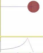
ps..I have attached an analysis scan showing the magnetic field intensity of a cylindrical conductor. The top is the wire, the bottom is the field magnitude plot. Note that on the far right the field magnitude is zero, this at the center of the wire. It increases linearly as you head to the wire surface. At the surface, it changes into the 1/r function. It never reaches zero, as this is a plot of a wire without a return conductor.
Cheers, John
Attachments
Last edited:
- Status
- Not open for further replies.
- Home
- General Interest
- Everything Else
- speaker cable myths and facts