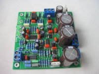
Some time ago I built this DAC and connected it via SPDIF (coax) to my CD player. Sounds great... no problems.
Recently I tried the same DAC on the SPDIF output of my PC. 44.1Khz and 48Khz worked fine in both 16 and 24 bits. 96Khz and 192Khz failed, both in 16 and 24 bits..
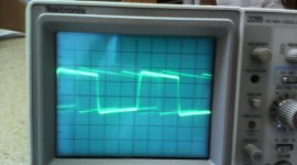
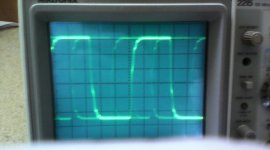
To find out what caused this failure, I connected a scoop to the cable. The waveforms @ 44.1 and 48 Khz looked nice (a somewhat rounded square-wave) and at good level.
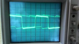
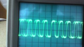
96 and 192 Khz waveforms looked more like a sawtooth/sharp-sinus and at a considerably lower level... not good (unloaded spdif line!). 96Khz level was a bit better than the 192Khz level...
So, now I need to find out what causes this deterioration of the waveform and level..
The options I came up with are:
- the PC card (Asus Xonar D2X) puts out a crappy SPDIF signal.
- the cable (common RCA) I used, ruins the signal.
But how to determine the real cause?
Or can I use a (cheap) fix to improve the wave-form quality and the signal-level?
Recently I tried the same DAC on the SPDIF output of my PC. 44.1Khz and 48Khz worked fine in both 16 and 24 bits. 96Khz and 192Khz failed, both in 16 and 24 bits..
To find out what caused this failure, I connected a scoop to the cable. The waveforms @ 44.1 and 48 Khz looked nice (a somewhat rounded square-wave) and at good level.
96 and 192 Khz waveforms looked more like a sawtooth/sharp-sinus and at a considerably lower level... not good (unloaded spdif line!). 96Khz level was a bit better than the 192Khz level...
So, now I need to find out what causes this deterioration of the waveform and level..
The options I came up with are:
- the PC card (Asus Xonar D2X) puts out a crappy SPDIF signal.
- the cable (common RCA) I used, ruins the signal.
But how to determine the real cause?
Or can I use a (cheap) fix to improve the wave-form quality and the signal-level?
Last edited:
Do you want to know which scoop etc.??- scope, probes, probe attenuator settings?
- Tek 2215
- probe 1x
- .2V/div
Probably you want to know something else.. please be more specific. Currently I'm not able to record/photograph the screen..
44 and 48 gave a bit over 3 div's (ca. 0.6Volts square-wave with rounded leading/falling edge)
96Khz : a bit under 3 div's (ca. 0.55V but more triangular)
192khz : 2 div's (0.4 V and even more triangular)
Tek 2215, 60meg, seems okay (spdif@192=12MHz). To see it as more-or-less sinewave.
- probe 1x
^^ might be that's the problem. You need 10x probe, with more-or-less known bandwidth, at least 50meg.
The reason - the probe has some input capacitance, stated for 10x mode operation. If you use it as 1x, you get lot more capacitance.
Tek P2100 has 14.5 pF-17.5 pF@ 10X and 80 pF-110 pF@1X.
If your probes are more like 50meg, you get something closer to 2x of the capacitance of P2100, thus 160-220pF.
Such capacitance at 12mhz is R=1/2pi*f*c=1/(2*3.14*12000000*220/1000000000000)=60ohm.
There is a series resistor on every SPDIF output, 75ohm. When connected to 60ohm impedance of capacitor, it should give you less than half of real unloaded voltage.
So it is OK, if your probe is 1x.
From your voltage levels it looks you've got 100mhz probes.
Try with 10x probe
S3tup, thanks for the directions how to use the probes in this case. Voltage levels now look better. Wave-shapes however do not improve towards an acceptable level...
44.1 and 48 still do look acceptable (but too much rounded imho)
96Khz shows a bad wave-shape (DAC reports "error")
192Khz is as bad as it was...
44.1 and 48 still do look acceptable (but too much rounded imho)
96Khz shows a bad wave-shape (DAC reports "error")
192Khz is as bad as it was...
Sketch the waveforms...
Show us your DAC input, PCB traces if possible, cable used etc
There is no correlation between the digital wave appearance and the audio out, apart from it getting so bad that you get no sound out.
it sounds like some signal integrity problem (I presume the DAC can handle these higher rate signals) as the sample rate goes up so does the data rate, and it seems it is this increased data rate that is causing the problem.
Things to try and measure, SPDIF output with a simple 75R resistor across the output of the sound card, look at data rates and RISE TIME for the various data rates. This should determine whether the output is getting corrupted before the cable etc.
Then repeat with the resistor at the end of your cable.
That should isolate some causes and parts of the signal chain.
Marce, thanks for your reaction.
- Yes, The receiving DAC is capable of 24/192.
- I'll try to measure the SPDIF output. But that requires some diy... and I don't know if I have the right parts in store...
- The wave-shape shows increasing deterioration due to bandwidth-limitations... so checking the SPDIF-out is a very good suggestion.
I'll keep you posted.
I've been thinking about the symptoms.. Decreasing wave-form with increasing frequency.. First point of interest is the cable, for I do not think that it's likely that electronics are THAT limited in bandwidth...
EDIT: The cable i've been using was meant for composite-video. which might explain the limited bandwidth and crippling the rather HF spdif signal.
My first action (before starting further investigation into the characteristics of the spdif output on the PC) is to try an other cable with better bandwidth-specs...
Let you know ...
Last edited:
Do you have RCA connector to plug directly to Xonar? Without a cable, just the connector.
Try measuring the thing directly on that plugged connector.
Do tou have resistors in your drawer? 75ohm, 100 in paralel with 300ohm, other resistor combos will work.
This way you eliminate the cable altogether, and see what's going on on Xonar's output.
Try measuring the thing directly on that plugged connector.
Do tou have resistors in your drawer? 75ohm, 100 in paralel with 300ohm, other resistor combos will work.
This way you eliminate the cable altogether, and see what's going on on Xonar's output.
Which is the length of cable you used?
Be sure that it is 75Ω cable. You can use a standard TV antena cable. This cable it is guaranteed to work until 500-800MHz and it is cheap and easy available. Check if the input of DAC it is 75Ω. If not put a 75Ω resistor to maintain the adaptation. Must be 75Ω to work on high sample rate.
Check if the output of your sound card it is 75Ω. Put the scope directly on SPDIF out without any resistor (output opened), note the voltage level, put a 75Ω resistor (can be made from 2-3 resistors to obtain 75Ω) and now the voltage level must be half if the output impedance it is 75Ω. Similar you can check the input impedance of the DAC, but you probably need a signal generator.
Because you have a scope it is easy to check the cables but be sure that you maintain the adaptation to 75Ω from output of sound card until input of DAC.
Anyway some pictures of the signal will help to identify the problem. So please post some photos.
Cable should be fine I tested my DAC through spdif with a simple RCA cable for music. And works fine with 24/192 signal. If the signal looks bad at the sound card, then it doens't have 75 ohm on it, or it goes through too many electronics.
Like this guys CD player. But it shouldn't be the case I think. Also from PC the spdif TTL signal looks really crapy without 75 ohm.
Like this guys CD player. But it shouldn't be the case I think. Also from PC the spdif TTL signal looks really crapy without 75 ohm.
The SP/DIF signal of the CDplayer from link looks ok. It is not perfect rectangular because of the transformer but without the transformer you will generate a ground loop and the problems can increase, by injecting noise on DAC ground.
A good line receiver should not have any problem with a signal like this. I'm asking how the signal after mods look at the input of receiver after 1-3 meters of cable.
Anyway a simple osciloplots without an adapted cable and good termination will not say anything about the quality of the signal at the input of a digital receiver.
It is the most comun mistake made (intentionally or not) by the people that post mods on industrial made equipments.
If you realy want to check the signal with a scope, you need to use an eye diagram/test at the input of receiver, after cable (adapted or not) with the receiver connected and using high impedance low capacity probe for the oscilloscope.
Having tested the other (real coax) cable: The shape of the 96Khz was improved, so the cable was one of the factors... The peal-level at all frequencies now looked OK. The 96K (on the DAC) unfortunately still showed the error-led.
192Khz still looked like a ragged saw-tooth ... SSo this will be the next stap:
First I need a RCA plug, which I will get tomorrow... together with some other stuff I need.
192Khz still looked like a ragged saw-tooth ... SSo this will be the next stap:
Do you have RCA connector to plug directly to Xonar? Without a cable, just the connector.
Try measuring the thing directly on that plugged connector.
Do tou have resistors in your drawer? 75ohm, 100 in paralel with 300ohm, other resistor combos will work.
This way you eliminate the cable altogether, and see what's going on on Xonar's output.
First I need a RCA plug, which I will get tomorrow... together with some other stuff I need.
I currently have trouble providing such screenshots, but I will try and see if I can provide them... Also tried to draw them in MS-paint.... dissaster with a LogitecTrackmanMace said:Without a sketch or screen shot of the waveforms we are playing in the dark, and we need the waveforms as I described earlier, once we isolate where the problem is occurring then we may find a solution....
An externally hosted image should be here but it was not working when we last tested it.
Attachments
Last edited:
An RCA with a 75R resistor soldered across the terminals makes a quick easy plug in checker for any 75r set up (for cable TV we had an F connector with a 75R across it, plug it in attach a scope and you get to see the output, caveat at its best driving a simple resistive load, then a cable with a 75R at the end, adds a cable to the equation).
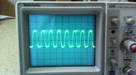
We've got a view!
Finally I've got the pics.
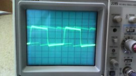
The first series is measured on the Sound-card chassis terminated with 75ohm.
44Khz, 48Khz, 96Khz and 192 Khz
So, this is what leaves the sound card
In the next mail I'll post the wave-forms at the end of the cable not terminated.
In the third mail, you'll see the wave-forms entering the DAC (which I yet have to make)
Finally I've got the pics.
The first series is measured on the Sound-card chassis terminated with 75ohm.
44Khz, 48Khz, 96Khz and 192 Khz
So, this is what leaves the sound card
In the next mail I'll post the wave-forms at the end of the cable not terminated.
In the third mail, you'll see the wave-forms entering the DAC (which I yet have to make)
Attachments
Last edited:
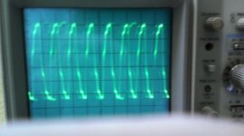
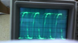
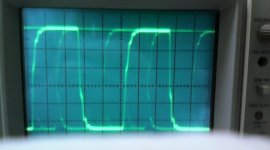
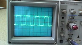
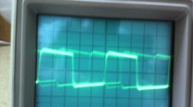
And the last pics
This is what the DAC sees at the entrance :
44Khz, 48Khz and 192Khz
To me the wave-forms do not look too bad.. but what do you think?
The voltage settings are 20mv/div + 10x on the probe (so 200mV/div)
This is what the DAC sees at the entrance :
44Khz, 48Khz and 192Khz
To me the wave-forms do not look too bad.. but what do you think?
The voltage settings are 20mv/div + 10x on the probe (so 200mV/div)
Attachments
- Status
- This old topic is closed. If you want to reopen this topic, contact a moderator using the "Report Post" button.
- Home
- Source & Line
- Digital Line Level
- SPDIF voltage-level