in fact, I do have a version that does that ")
http://www.diyaudio.com/forums/digi...b-interface-audio-widget-177.html#post3125474
link to source: Index of /spdif_meter_simple
this is standalone source that just runs in this 'private' arduino. its not part of the lcduino but it would be easy to convert this code, posted, to the lcd display.
when I finally get around to doing some wm8804/5 coding, I'll bring this bit of code over and it will show up on the lcd display.
for now, though, this should be enough to get you started. any questions, just ask.
Last edited:
as long as you can grab wordclock (ie, the 44.1khz etc freq) and wave shape it a bit and feed it into the arduino on the right pin, it should decode it for you.
I've seen some small 8char lcd's (easy to fit in a place that wasn't expecting a large lcd) and that would be enough to hold the several digits you need to display 192.0k or something.
or, get one of the sparkfun 4 digit led modules and just interface this arduino to that.
btw, I think the reason I went this with as a standalone chip is that I didn't have to worry about any other task bumping into the software freq. counter. which is all this chip is really doing. for a $5 chip and some small parts, I didn't see the immediate need to merge this in and have to share time on 1 cpu.
have fun
So, you may think that I could go around all the trouble and just plug in one of those to provide spdif coax switching? They are high-Q signal relays, my intention is to select one to a DAC input at a time.I seem to have luck with spdif. wiring never seems to be critical and receivers always lock on. I know, I know, the impedance gods will curse me for saying so. the audio sounds fine to me and no matter what I do, it never gets better or worse.
the proto was also just hand wired; but again, spdif seems to just plain work no matter what wire or connectors I use.
I have seen all kind of multiplexer solutions but, why not avoid all troubles and just go with good old plain relays? Is impedance matching so important at that level, having in mind that you end up using cheap RCA chassis conector and no less cheaper interconnect cables, and everyting use to work pretty fine?
Eight DPDT Signal Relay Module Board 12VDC SKU177007 | eBay
Best regards
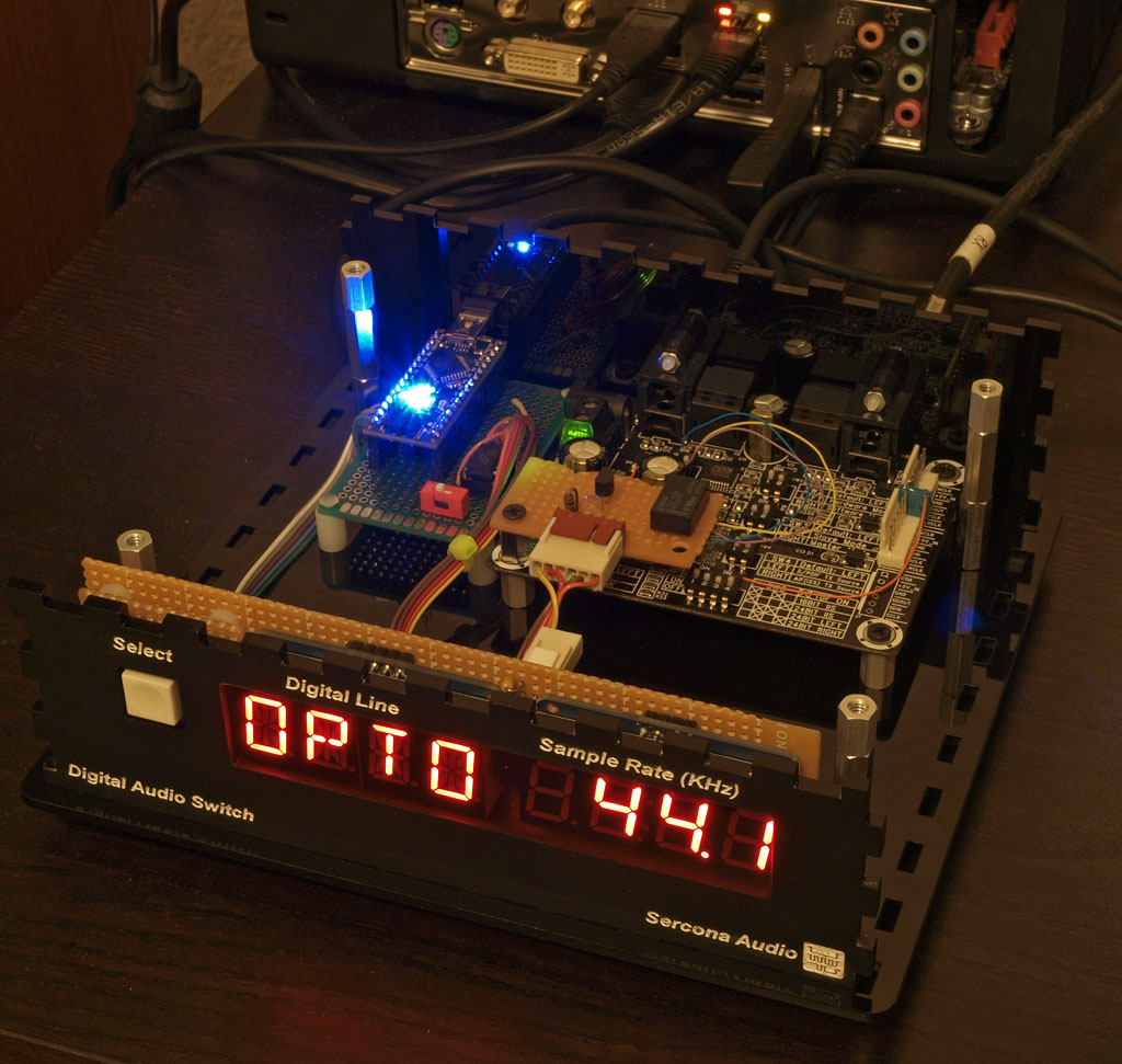
updating an old thread, but going in a slightly new direction. here's a front panel I just built that I plan to integrate into an spdif switch box:
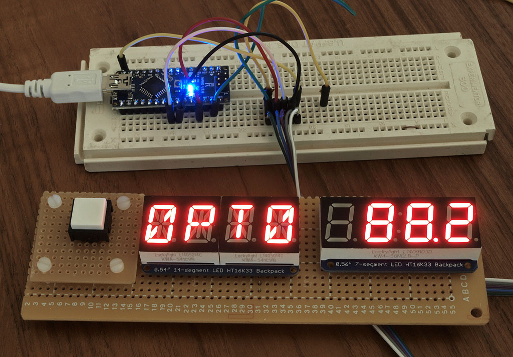
I decided to try using some led backpack modules, one alpha and one numeric. you can see the kind of info I plan to have on each
the single button will let you cycle thru the inputs and the alpha display will show the name of the input you selected. currently I plan to have coax and opto but I could add more easily enough.
the new cool part is the samplerate display. again using an arduino, I have frequency counter logic working that picks out the wordclock from an spdif rx chip and shows the value on that 2nd display. I always wanted to show the real SR of what I am listening to and this will do it, up to 192k.
for the back-end, just to get things going, I am hacking a 'sure electronics' wm8804 module, just for simplicity.
that only has opto and coax inputs, so that's all I can select from, currently. whatever input is selected, both media types are driven on the output jacks.
the module breaks out i2s for you so tapping into wordclock is trivial. map it from 3.3v to 5v for the arduino, feed into pin 5 for freq counter input on the arduino and you're in business.
more notes and photos as the project progresses. yes, source will be posted when I'm done.
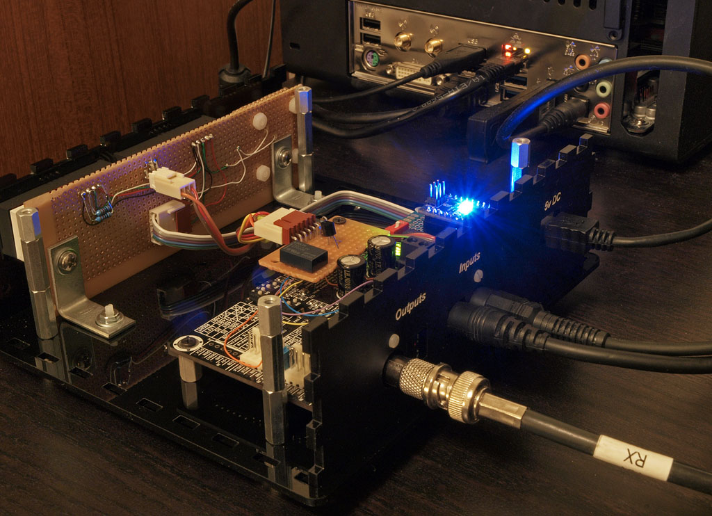
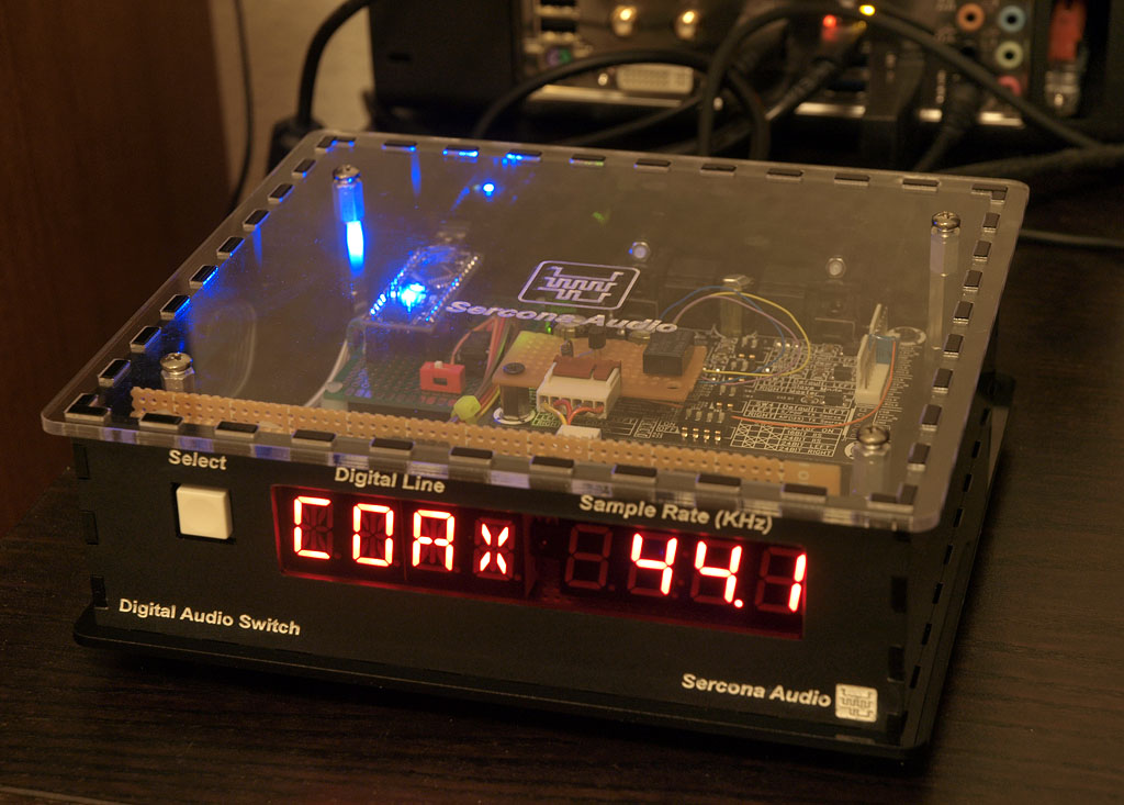
wolfson eval board, my own bodge-board (relay) and the arduino display stuff:
actually in use. simply having a .1uf cap in series with the 3.3v wolfson wordclock and the arduino 5v logic input - it was enough for the counter logic to lock on and trigger. really simple interface!
nothing special about the.1u its just a floor capacitor. you know, you find lots of them on your workbench floor and they're good for nearly any purpose...
(grin)
Glad to see you are still alive and well!
Is that WM8804 board from Sure Electronics?
Glad that you popped this up to the top. I like the rate indicator and I've made a local copy of that Arduino pde. Seems to compile with minor updates.
Will look for near term updates here...
Is that WM8804 board from Sure Electronics?
Glad that you popped this up to the top. I like the rate indicator and I've made a local copy of that Arduino pde. Seems to compile with minor updates.
Will look for near term updates here...
On that subject, you are referring to your panel cutouts and lettering? This has been one stumbling block for me for sure - how to encase my projects in a professional manner.I have to say, as a builder, I can divide my life into two parts: the time when I didn't have access to a laser cutter, and the time after which I did
Is this a commercial venture that you use or just a personal connection? For instance I know that the company Pololu in Las Vegas will do custom laser cutting and engraving on a range of materials. I've haven't used them but have been interested in trying them out... For more info, see:
Pololu Custom Laser Cutting (link: pololu.com/product/749)
Also, do you have all the panels cut and engraved or do you only do the front and back, and get the other pieces somewhere else?
during one of my unemployed periods of time (which, sadly, happen more and more as I get beyond the golden age that software companies prefer to hire from, sigh) I joined tech shop in the bay area and I do my own laser cutting now. its not something I can easily draw out and send out to be done; the first version never fits and there are always some tweaks needed here and there.
the lettering is something I do that is extra: I etch the lettering deeply into the plastic (sometimes by doing a 2nd or 3rd pass after raising the laser bed a click or two, to set the focus down deeper), then I leave the paper masking on and rub some white acrylic paint into the lettering voids. simply using plastic gloves, I rub the white paint in with my fingers to press it in (works better that way). let it dry for 10 minutes or so, then peel the backing off and fix-up any spills or over-paint. if you do it before it fully dries, you can make it look pretty good, at least at a normal viewing distance. if you look up close, you'll see the 'handmade details' but from shelf viewing, its completely fine. can't compete with pro places like front-panel-express but they charge an arm and a leg for their work. I can't justify it for most projects.
as long as what I want can be done on 18"x24" plastic, I'm all set. that's what the epilogue printers at the TS are limited to.
you can cut up to 1/2" plastic but I usually use 1/8" for most boxes and 1/4" for some things that need more strength.
this is where you go to get a quick box designed for you, online, in pdf format:
BoxMaker
amazingly easy. try it. it will write a pdf for you and you can import that into any cad program, then draw into the boxes that the pdf created for you, to make circles and squares for cutouts of ports and switches and such.
its extremely satisfying to walk into techshop, buy some plastic sheets there, cut it on the epilogue and walk out with it that same day. once you live thru that, there's no going back again to the old school manual methods of box making and cutting
if you are driving distance to techshop, you really should go for a free 15min tour. for people who build things, its as close to nirvana as you'll get.
they also have proper metal and wood cnc's, too. but laser cutting is so much easier and the materials are cheap, too ($15 for a 1/8" sheet of 18x24).
both
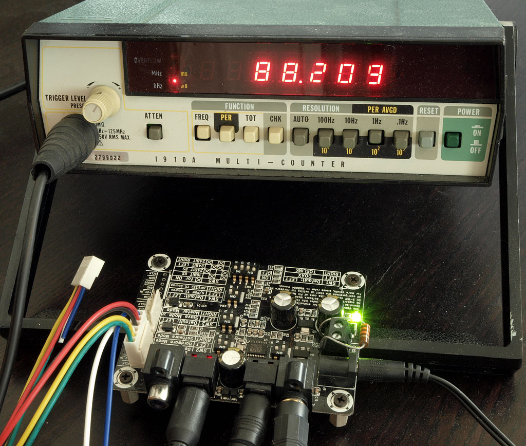
its not a strict freq counter. I didn't see the purpose in showing 44.102 or anything like that. so, I do run a freq count routine in the arduino but I allow slop of 10% (to pick a number) above and below, just to allow for software freq count timing to be off and still show the audio rate that is closest to the sampled value on the cpu pins. its configurable so you can set the 'bandwidth' of the 'filter' to be what you think makes sense. its purpose is not to show how accurate your bitrate is but to show -which- Fs you are running, out of the standard ones.
I have coded support for 32, 44, 48, 88, 96, 176 and 192. those are the only standards that are likely to be seen in spdif (even the 32 is arguable these days, but I do have some ancient 32k LP/longplay DAT tapes and if I ever fix up my dat player, I really would see 32k coming out of the spdif port).
I have some ideas on how to get bit depth, too, but that's not a big priority for me right now (it would be nice to at least show that audio is 16, 20 or 24 bits).
@linuxworks, do you mind posting the schematic for the switching section please? ...and any kind of exotic parts used for the input switching/conversion to TTL/etc. ...I've lost tracked of your final implementation; there is so much post around different forums regarding your spdif solution...
I wish I had a switch fabric, but I don't really (yet). still working on it.
what I did use was a premade demo board from ebay/china (sure electronics):
WM8804 s PDIF Toslink to IIS Converter I2S Codec Project Integration DIY | eBay
it came in a week (fast) and I bought that module before - it was the same one I bought a few years ago.
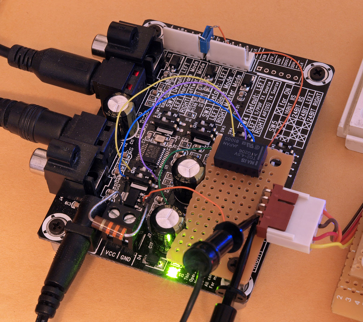
the only thing I had to do was to tap into its switches to select opto or coax. admittedly it was a hack and I used a relay to simulate the 2 dip switches' states (flip one or the other; it just connects the one that is selected to the input of the wolfson). it does not really switch, but the wolfson does wave-shape and retime, which I consider to be a good and useful thing anyway.
so, if you look at the pcb and my wires, you'll see the 3 wire wrap taps I made into the top left select switches. that is the key for this board, at least. the rest of the switches are left alone as they set the mode of the board.
eventually, I will find a good circuit (or design one on a real pcb) to do input selection for spdif but this build was more about the box and firmware, leaving the switch part to be better re-done later.
it does work though and it was cheap to do, so if you are in a hurry, its not really that bad. but its not at all what I have in mind for a final product.
what I did use was a premade demo board from ebay/china (sure electronics):
WM8804 s PDIF Toslink to IIS Converter I2S Codec Project Integration DIY | eBay
it came in a week (fast) and I bought that module before - it was the same one I bought a few years ago.
the only thing I had to do was to tap into its switches to select opto or coax. admittedly it was a hack and I used a relay to simulate the 2 dip switches' states (flip one or the other; it just connects the one that is selected to the input of the wolfson). it does not really switch, but the wolfson does wave-shape and retime, which I consider to be a good and useful thing anyway.
so, if you look at the pcb and my wires, you'll see the 3 wire wrap taps I made into the top left select switches. that is the key for this board, at least. the rest of the switches are left alone as they set the mode of the board.
eventually, I will find a good circuit (or design one on a real pcb) to do input selection for spdif but this build was more about the box and firmware, leaving the switch part to be better re-done later.
it does work though and it was cheap to do, so if you are in a hurry, its not really that bad. but its not at all what I have in mind for a final product.
- Status
- This old topic is closed. If you want to reopen this topic, contact a moderator using the "Report Post" button.
- Home
- Source & Line
- Digital Line Level
- spdif switch module for LCDuino